Ultrasonic distance sensors with Pd in Bela
The ultrasonic distance sensors are usually digital, not analog. If this is the case, you're trying to read a digital signal as analog, which doesn't make much sense. This sensor has two pins, a trigger and an echo. You have to send a high voltage to the trigger pin, then pull it low, and read the echo pin which will help you compute the distance based on the time it took for this trigger pulse to arrive back at the echo pin.
The code below (copied from Arduino'g Project Hub), uses Arduino's pulseIn() function, to compute the distance:
// Define Trig and Echo pin:
#define trigPin 2
#define echoPin 3
//  Define variables:
long duration;
int distance;
void setup() {
  // Define  inputs and outputs:
  pinMode(trigPin, OUTPUT);
  pinMode(echoPin, INPUT);
  //Begin Serial communication at a baudrate of 9600:
  Serial.begin(9600);
}
void  loop() {
  digitalWrite(trigPin, LOW);
  delayMicroseconds(5);
  digitalWrite(trigPin,  HIGH);
  delayMicroseconds(10);
  digitalWrite(trigPin, LOW);
  // Read  the echoPin, pulseIn() returns the duration (length of the pulse) in microseconds:
  duration = pulseIn(echoPin, HIGH);
  // Calculate the distance:
  distance=  duration*0.034/2;
  // Print the distance on the Serial Monitor
  Serial.print("Distance  = ");
  Serial.print(distance);
  Serial.println(" cm");
  delay(1000);
}
I searched online and found the source of this pulseIn() function in Arduino's forum, which is this:
/*
  wiring_pulse.c - pulseIn() function
  Part of Arduino - http://www.arduino.cc/

  Copyright (c) 2005-2006 David A. Mellis

  This library is free software; you can redistribute it and/or
  modify it under the terms of the GNU Lesser General Public
  License as published by the Free Software Foundation; either
  version 2.1 of the License, or (at your option) any later version.

  This library is distributed in the hope that it will be useful,
  but WITHOUT ANY WARRANTY; without even the implied warranty of
  MERCHANTABILITY or FITNESS FOR A PARTICULAR PURPOSE.  See the GNU
  Lesser General Public License for more details.

  You should have received a copy of the GNU Lesser General
  Public License along with this library; if not, write to the
  Free Software Foundation, Inc., 59 Temple Place, Suite 330,
  Boston, MA  02111-1307  USA

  $Id: wiring.c 248 2007-02-03 15:36:30Z mellis $
*/

#include "wiring_private.h"
#include "pins_arduino.h"

/* Measures the length (in microseconds) of a pulse on the pin; state is HIGH
 * or LOW, the type of pulse to measure.  Works on pulses from 2-3 microseconds
 * to 3 minutes in length, but must be called at least a few dozen microseconds
 * before the start of the pulse. */
unsigned long pulseIn(uint8_t pin, uint8_t state, unsigned long timeout)
{
    // cache the port and bit of the pin in order to speed up the
    // pulse width measuring loop and achieve finer resolution.  calling
    // digitalRead() instead yields much coarser resolution.
    uint8_t bit = digitalPinToBitMask(pin);
    uint8_t port = digitalPinToPort(pin);
    uint8_t stateMask = (state ? bit : 0);
    unsigned long width = 0; // keep initialization out of time critical area

    // convert the timeout from microseconds to a number of times through
    // the initial loop; it takes 16 clock cycles per iteration.
    unsigned long numloops = 0;
    unsigned long maxloops = microsecondsToClockCycles(timeout) / 16;

    // wait for any previous pulse to end
    while ((*portInputRegister(port) & bit) == stateMask)
        if (numloops++ == maxloops)
            return 0;

    // wait for the pulse to start
    while ((*portInputRegister(port) & bit) != stateMask)
        if (numloops++ == maxloops)
            return 0;

    // wait for the pulse to stop
    while ((*portInputRegister(port) & bit) == stateMask) {
        if (numloops++ == maxloops)
            return 0;
        width++;
    }

    // convert the reading to microseconds. The loop has been determined
    // to be 20 clock cycles long and have about 16 clocks between the edge
    // and the start of the loop. There will be some error introduced by
    // the interrupt handlers.
    return clockCyclesToMicroseconds(width * 21 + 16);
}
This is already getting complicated, as pulseIn() uses other functions which should be found and translated to Pd. I guess the best thing you can do is try to translate the first code chuck in this reply to Pd, and when you read a high voltage in the echo pin, do some math to calculate the distance.
In essence, set a digital input and a digital output pin on the Bela, trigger the output pin with a high and low signal, and keep reading the input pin (you should probably use a pull-down resistor there), until you get a high. Calculate the time it took with the [timer] object and do some simple math to get the distance. Do that with distances you know first, and then use the rule of three based on the known distance and the time you get. At least, that's how I would try to get this to work.
Another solution is to use an infrared proximity sensor, which is analog, and it's probably much easier to use. But this gets the proximity of obstacles right in front of it only, while the ultrasonic range finder has a wider field where it can detect obstacles.
 posted in technical issues
Higher order filter in PD extended
@kyro By non-linear I was referring to things like [pow~] getting stuck in the feedback loop, not a correct terminology but one I fall back on with synths because it was a common term in the synth diy community 20 years ago to refer to anything that is not the normal distortion/filtering type stuff in a filters feedback loop.
@manuels The magic of the moog (as in minimoog) is primarily in the output amp which affects the entire filter and is why the ARP version sounds so different, they 'fixed' it and lost the characteristic flavor of the mini's filter. The output amp on the mini's filter does not have anywhere high enough of an impedance to deal with the ladder which drags down frequency response and distorts things, feedback loop comes off output amp so nothing in the filter is untouched by the output amps flaws and it is more the heart of the filter than the ladder. Later Moog ladders are closer to the ARP version, output amp has a high enough impedance and we loose most of the mini's character but we get a decent response in the upper registers in trade.
Most of the classic VCFs are just cascaded 6db filters with a feedback loop for resonance and is my standard, the various 'proper' filters created in the digital world are lacking in many ways to my ears. The cascaded nature of many circuits in the analog world is part of what the digital world is missing, in a 4 pole filter that means we at least have input amp, 4 filter stages, output stage and feedback each giving their own distrotion and frequency characteristic. The filter stages we try and balance and get them to cancel out any quirks to work together but they still have an individual character and input, output and feedback have a very strong character which gives us a rather dynamic result when everything is combined.
And since analog feedback is basically delayless (which in digital land is of course impossibe)
Check my thread on feedback which actually came about because of trying to get a decent filter executed in pd, getting closer.
 posted in technical issues
converting arduino sketches to run in Pd for Bela
@Coalman
To give you even more options:
If you want to patch everything in PD but no hardware change, you could connect an old laptop, or Bela (Beagle Board) or Pi and Arduino via USB (as virtual serial port) and use Firmata or PDuino (available in Deken) to access Arduino's GPIOs from PD.
Not sure if this is the case for the async PWM. (But you could add that function as exception on the Arduino side with input from serial.)
What speed is the PWM? Higher than audio Niquist (probably yes)?
Else you could just do PWM in PD.
Most, if not all popular (micro)controllers provide asynchronous PWM-pins today. Read the datasheets.
Did you already search your answers?
https://forum.bela.io/d/1009-basic-pwm-question/
https://forum.pdpatchrepo.info/topic/12112/raspberry-pi-gpio-and-puredata-does-it-work/
https://github.com/owenosborn/rpi_gpio
There should be many examples for, PD <-> GPIOs on Bela, as this is what it's all about.
reason for this inefficiency is that my knowledge is fairly limited on these platforms.
Maybe decide for one board (or an old laptop with comport) for all projects, and grow with it.
 posted in I/O hardware diy
converting arduino sketches to run in Pd for Bela
hello! this question intersects with Pd even if it is not about Pd specifically...
I currently have several (installation) pieces in which the sound is run from Pd and then I have motors or sensors being run off other things.
This means that in one case I am using a raspberry pi for the Pd part and an Arduino mega for the motor part
In another case I have Pd running on a Bela/BBB and then an Arduino doing the motor stuff.
The reason for this inefficiency is that my knowledge is fairly limited on these platforms. However, it is annoying to have to use the extra gear when I don't have to. Especially because I know that both the raspberry and the Bela have pins that could be used in place of the arduino for this purpose. Since the Bela is a simpler case and the pins can be addressed directly from Pure Data, I will ask about that and leave the Raspberry behind for now (as I think I would end up running Pd AND Arduino on that board anyway, whereas with Bela, one can easily address the pins from inside Pd without any other programs or libraries).
My question is this: does anyone know how the standard mappings of pins Analog/Digital/and PWM pins on the Arduino lines up on the Bela? Does the Bela have have PWM pins like, for example pins 8,9, 10,11 on Arduino Mega or Dueminanove? And if so, what is the best way to address them from Pure Data? Basically, I'd like to convert my already very simple Arduino sketches over to Pd, so that both motors and Audio can run from the same patch.
I know this isn't specifically a Pd issue but I have asked a related question on the Bela forum but didn't get an answer so I hoped someone might know or be able to suggest a resource over here...
I have traversed the Bela documentation already of course....and will continue with that meanwhile.
Jorge
 posted in I/O hardware diy
warble tones considered harmful?
Sounds BS to me. DC would damage speakers but you can't detect DC by ear (for obvious reasons).
Interestingly, though, FM easily suffers from DC while phase modulation seems not to, at least for ratio >= 1.
hjh
 posted in Off topic
Copy larger array (1mb) to smaller array (64kb) with visual definable startpoint?
Pd prints floating point numbers with 6 decimal digits only, but it may be accurate below that (or it might not be).
In this specific case, 1048580 in fact requires only 6 decimal digits of precision! 1.04858 * 10^6 happens to be exact. So the number did come out right.
1048580 by my calculation needs 21 bits. In 32 bit floating point, the mantissa has 24 bits of precision (23 encoded bits + 1 implicit bit). So 1048581 and 1048579 should also be precise internally, though they will not print the 1s digit.
hjh
posted in technical issues
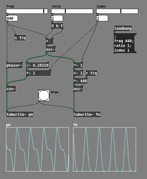
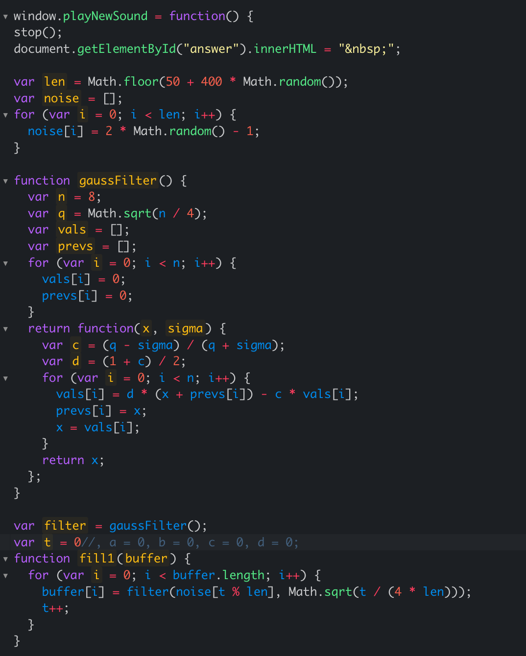
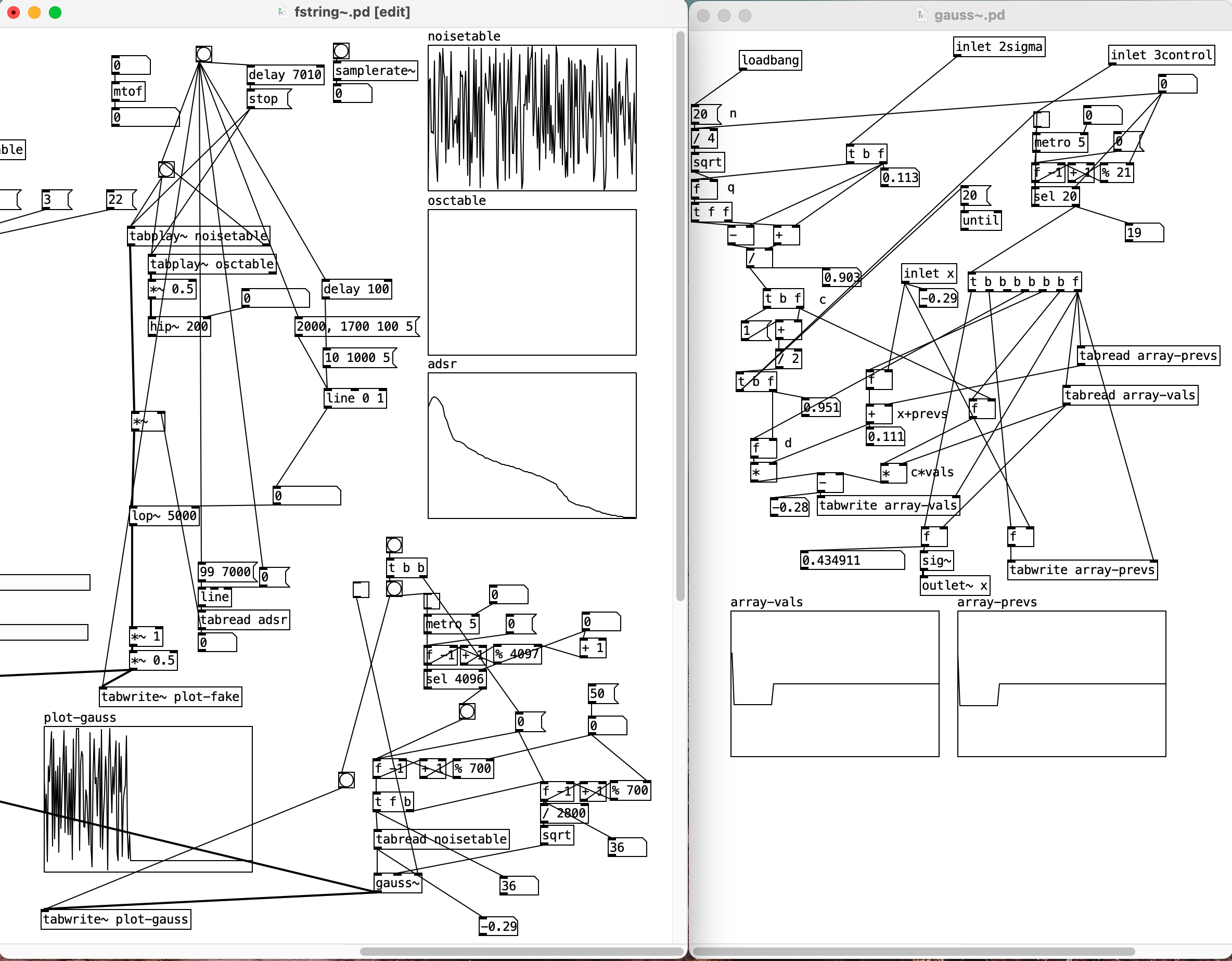
Karplus-Strong alternative help
I found this reddit post regarding an alternative to the karplus-strong algorithm to generate string sounds. But the snippet provided is in javascript. I tried implementing it in pd but am having a tough time transferring all the JS idioms into pd. Kindly help. Also, please skip the suggestion of using [expr].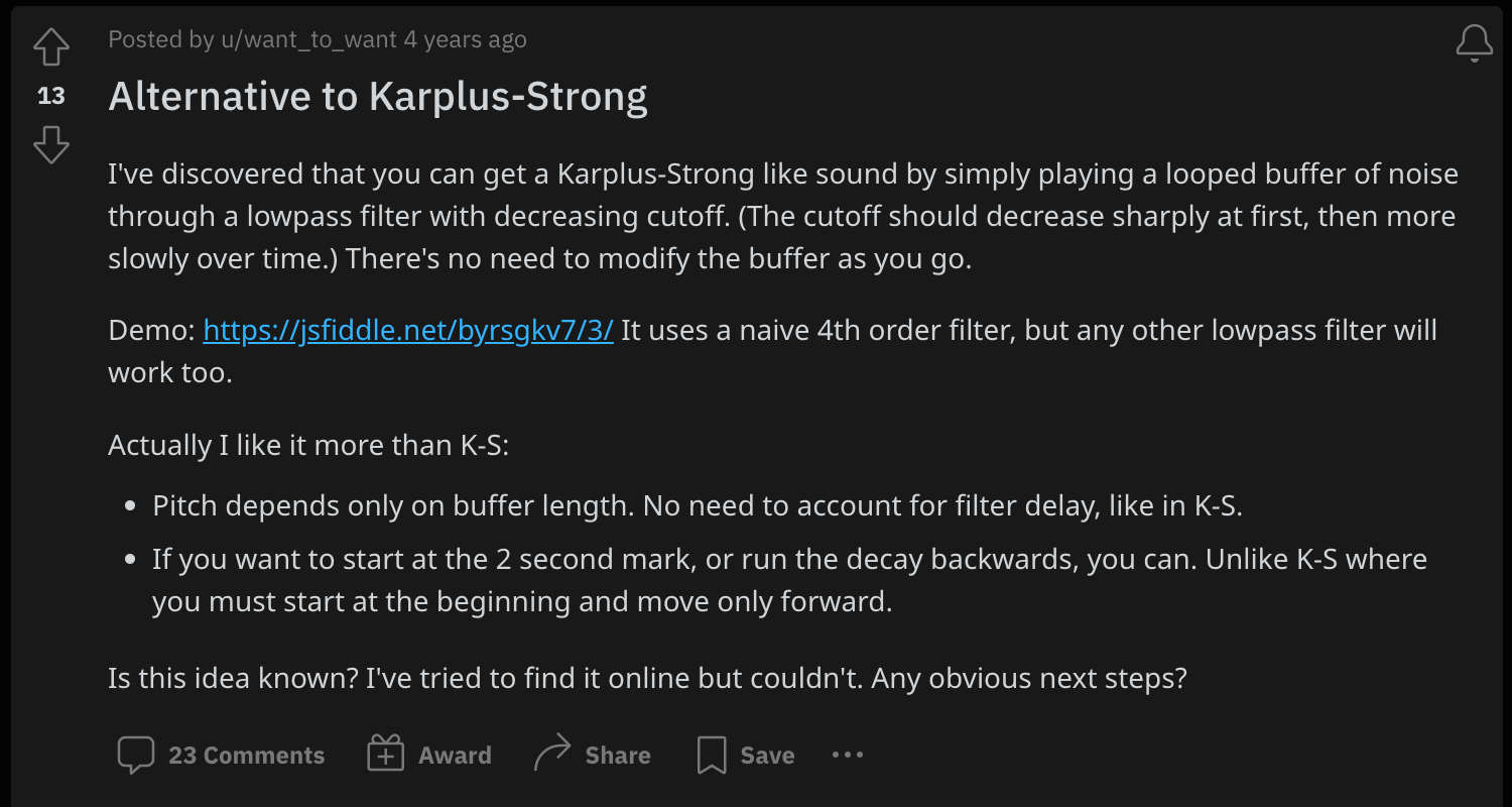
 posted in technical issues
Math detail problem of numbers larger than six or so decimals
@raynovich I agree with your larger point. I don't understand why there isn't more interest in double precision floats. Single precision floating point only gives you so many digits--I think just one or two digits past where Pd is truncating. You can get control of those digits using ugly tricks like this:
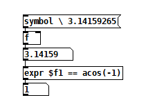
The backslash-escaped space before the pi digits stops Pd from truncating it.
 posted in technical issues
Cannot use any digital outputs except 0-7 on Teensy 4.1 with StandardFirmata and Pduino
after further testing.... pins 8-13 also work fine as digital outs. pins 28-37 are the problem pins. they work as digital inputs without issue, but do not work as digital outs. I've also tried it with a second teensy to rule out a bad board... same problem
UGH
 posted in technical issues
Large number representation in pd
@60hz double precision would solve the bit-depth issue, but the textual representation of numbers (floats) would also have to be changed to add precision. (I haven't checked if pd-double does this or not.. katja's page makes it seem like it does though)
here is her description from https://www.katjaas.nl/doubleprecision/doubleprecision.html :
You have probably noticed that single precision floats are represented in Pd with a maximum of 6 significant digits. This is done to hide inconsistencies like 33 * 0.3 = 9.900001, which happens when 7 decimal digits are shown. The limitation to 6 significant digits is however very annoying when we want to type or see large integers, like indexes of long audio buffers.
In calculations, Pd can use all integers from 0 to 2^24 = 16,777,216, over 16 million. Numbers with up to 8 decimal digits. But in the GUI, 1 million is shown in scientific notation as 1e+06. This scientific notation also uses a maximum of 6 significant digits. Therefore, the next representable number is 1.00001e+06, that is 1 million and 10. See below how the result of 2^20 is rounded in the GUI, as an example. The fact that numbers are also stored with patches this way, makes things worse. At 44100 Hz samplerate, one million samples is about 23 seconds - not at all that much. Longer audio buffers are allowed, but handling them in the GUI becomes tricky.
 posted in technical issues