Trying to reproduce a sound with Pd
@JMC64 You would need to look up the specs of the VCF on the manufactures website and find its frequency range. They will most likely give the range in hz, so if they say it goes from 8hz to 16khz that would roughly be C1 to C11, so halfway would be C6 or roughly 262hz, remember that frequency is not linear! You can use a chart like http://subsynth.sourceforge.net/midinote2freq.html to convert between note names and hertz or you can have pd do the math for you with the [mtof] and [ftom] objects. Also remember that you do not need to get perfect frequencies, those small knobs have poor resolution and being analog have a fairly wide tolerance, if you went through a dozen of those modules you would find that 0.5 would be slightly different on each of them, so just get close and then tune by ear to perfection.
You can do the same for any module and any parameter, you just need to convert the numbers differently, a VCA will likely have its specs in decibells and a CV input or output in volts.
EDIT: Should mention, you need to look at what the frequency range of the cutoff knob is, not the VCF. Sometimes a VCF or VCO will have a larger range than can be reached by just its frequency knob, the CV inputs can often extend it, so the knob may only go bring you to C8, but a +5 volt signal into the CV input would bring you to C13 because frequency goes up one octave for every volt in a V/oct system like the Doepfers. Generally they will give the tuning range of the knob separately if the VCF can sweep beyond the range of the knob, most modules do not do this though and you should not have to worry about it unless it gives two different values.
 posted in patch~
Having lots of switches into Pd
@alexandros now pwm and digital output work fine, but when I try to merge with digital and analog inputs it goes wrong. the leds flicker randomly. If you remove the code below
// do input pins: flicker stops. :/
int outPins[3] = {2, 4, 7};

int pwmPins[6] = {3, 5, 6, 9, 10, 11};

// a global variable to hold which LED we want to control (either digital or PWM)
int channel = 0;

int inPins[2] = {12, 13};

int analogPins[8] = {0, 1, 2, 3, 4, 5, 6, 7};

void setup() {

   for (int i = 0; i < 3; i++) {
    pinMode(outPins[i], OUTPUT);
  }
    for (int i = 0; i < 6; i++) {
    pinMode(pwmPins[i], OUTPUT);
  }
    for(int i = 0; i < 2; i++) {
    pinMode(inPins[i], INPUT);
  }

  pinMode(A0, INPUT_PULLUP);
  pinMode(A1, INPUT_PULLUP);
  pinMode(A2, INPUT_PULLUP);
  pinMode(A3, INPUT_PULLUP);
  pinMode(A4, INPUT_PULLUP);
  pinMode(A5, INPUT_PULLUP);
  pinMode(A6, INPUT);
  pinMode(A7, INPUT);

//DEFAULT works with thermistors,
//INTERNAL with transitor thermostats
  analogReference(DEFAULT);

  Serial.begin(115200);

}

void loop() {

  //do output pins:

  if (Serial.available()) {
    static int temp;
    byte in = Serial.read();
    if (isDigit(in)) temp = temp * 10 + in - '0';
    else if (in == 'c') {
      channel = temp;
      temp = 0;
    }
    else if (in == 'd') {
      digitalWrite(outPins[channel], temp);
      temp = 0;
    }
    else if (in == 'p') {
      analogWrite(pwmPins[channel], temp);
      temp = 0;
    }
  }

  // do input pins:

Serial.print("analog"); // use "knobs" as a keyword so you can receive
  // the knob values as a list with a [r analog] in Pd
  for(int i = 0; i < 8; i++){
    unsigned int analogVal = analogRead (analogPins[i]);
    Serial.print(" "); // first print a white space to separate the "knob" keyword from the values
    // and the values from each other
    Serial.print(analogVal); // then  print the actual knob value
  }
  Serial.println(); // finally print a newline character to denote end of data for keyword "knobs"

  Serial.print("digital");
  for(int i = 0; i < 2; i++) {
    unsigned int digitalVal = digitalRead(inPins[i]);
    Serial.print(" ");
    Serial.print(digitalVal);
  }
  Serial.println();
}
 posted in I/O hardware diy
Having lots of switches into Pd
@alexandros
This code sort of works with wip_multiple_PWM.pd
// merging works but pwm leds are choppy.

// number of elements in arrays need to
// match for() cycles in void setup and void loop
int pinsIn[2] = {2, 4};
int pinsAnalog[8] = {0, 1, 2, 3, 4, 5, 6, 7};

int pin = 0;
int val = 0;
int pinsOut[2] = {7, 12};

//TMP setup pwm:

// variables to hold pin numbers
int pwmLED1 = 3;
int pwmLED2 = 5;
int pwmLED3 = 6;
int pwmLED4 = 9;
int pwmLED5 = 10;
int pwmLED6 = 11;

// variables to hold pin states
int pwmLEDvalue1;
int pwmLEDvalue2;
int pwmLEDvalue3;
int pwmLEDvalue4;
int pwmLEDvalue5;
int pwmLEDvalue6;

//should this be omitted and use the a
// variable to hold and assemble incoming data
int temporary;

//END TMP pwm setup

void setup()
{
  //set up a total of pins for digital input (has to match number of elements in array)
  for(int i = 0; i < 2; i++)
  pinMode(pinsIn[i], INPUT);

  for (int i = 0; i < 2; i++) {
    pinMode(pinsOut[i], OUTPUT);
    digitalWrite(pinsOut[i], LOW);
  }

//DEFAULT works with thermistors,
//INTERNAL with transitor thermostats

  analogReference(DEFAULT);

  pinMode(A0, INPUT_PULLUP);
  pinMode(A1, INPUT_PULLUP);
  pinMode(A2, INPUT_PULLUP);
  pinMode(A3, INPUT_PULLUP);
  pinMode(A4, INPUT_PULLUP);
  pinMode(A5, INPUT_PULLUP);
  pinMode(A6, INPUT);
  pinMode(A7, INPUT);

//TMP test pwm setup:

  pinMode(pwmLED1, OUTPUT);
  pinMode(pwmLED2, OUTPUT);
  pinMode(pwmLED3, OUTPUT);
  pinMode(pwmLED4, OUTPUT);
  pinMode(pwmLED5, OUTPUT);
  pinMode(pwmLED6, OUTPUT);

  Serial.begin(115200); // perhaps use a faster baud rate
}

void loop()
{
  Serial.print("knobs"); // use "knobs" as a keyword so you can receive
  // the knob values as a list with a [r knobs] in Pd
  for(int i = 0; i < 8; i++){
    unsigned int knob = analogRead (pinsAnalog[i]);
    Serial.print(" "); // first print a white space to separate the "knob" keyword from the values
    // and the values from each other
    Serial.print(knob); // then  print the actual knob value
  }
  Serial.println(); // finally print a newline character to denote end of data for keyword "knobs"

  // the same technique applies to the switches too
  // receive the switch values as a list with [r switches]
  Serial.print("switches");
  for(int i = 0; i < 2; i++) {
    int switchVal = digitalRead(pinsIn[i]);
    Serial.print(" ");
    Serial.print(switchVal);
  }
  Serial.println();

  //handle digital outputs
  if (Serial.available()) {
    static int temp;
    byte in = Serial.read();
    if (isDigit(in)) {
      temp = temp * 10 + in - '0';
    }
    else if (in == 'p') {
      pin = temp;
      temp = 0;
    }
    else if (in == 'v')  {
      val = temp;
      temp = 0;
      digitalWrite(pinsOut[pin], val);
    }
}

//TMP merge test PWMs:
while(Serial.available()){
     byte inByte = Serial.read();
     if((inByte >= '0') && (inByte <= '9'))
       temporary = 10 * temporary + inByte - '0';
     else{
       if(inByte == 'p'){
         pwmLEDvalue1 = temporary;
         temporary = 0;
       }
       else if(inByte == 'q'){
         pwmLEDvalue2 = temporary;
         temporary = 0;
       }
       else if(inByte == 'r'){
         pwmLEDvalue3 = temporary;
         temporary = 0;
       }
       else if(inByte == 's'){
         pwmLEDvalue4 = temporary;
         temporary = 0;
       }
       else if(inByte == 't'){
         pwmLEDvalue5 = temporary;
         temporary = 0;
       }
       else if(inByte == 'u'){
         pwmLEDvalue6 = temporary;
         temporary = 0;
       }
     }
     analogWrite(pwmLED1, pwmLEDvalue1);
     analogWrite(pwmLED2, pwmLEDvalue2);
     analogWrite(pwmLED3, pwmLEDvalue3);
     analogWrite(pwmLED4, pwmLEDvalue4);
     analogWrite(pwmLED5, pwmLEDvalue5);
     analogWrite(pwmLED6, pwmLEDvalue6);
     //digitalWrite(dspLED, dspLEDstate);
   }
}
This is the code without PWM control. It works fine.
//number of elements in arrays need to match for() cycles in void setup
int pinsIn[4] = {6, 7, 8, 9};
int pinsAnalog[8] = {0, 1, 2, 3, 4, 5, 6, 7};

int pin = 0;
int val = 0;
int pinsOut[4] = {2, 3, 4, 5};

void setup()
{
  //set up a total of pins for digital input (has to match number of elements in array)
  for(int i = 0; i < 4; i++)
  pinMode(pinsIn[i], INPUT);

  for (int i = 0; i < 4; i++) {
    pinMode(pinsOut[i], OUTPUT);
    digitalWrite(pinsOut[i], LOW);
  }
//DEFAULT works with thermistors,
//INTERNAL with transitor thermostats
// ELLER var det tvartom???
  analogReference(DEFAULT);

  pinMode(A0, INPUT_PULLUP);
  pinMode(A1, INPUT_PULLUP);
  pinMode(A2, INPUT_PULLUP);
  pinMode(A3, INPUT_PULLUP);
  pinMode(A4, INPUT_PULLUP);
  pinMode(A5, INPUT_PULLUP);
  pinMode(A6, INPUT);
  pinMode(A7, INPUT);

  Serial.begin(115200); // perhaps use a faster baud rate
}

void loop()
{
  Serial.print("knobs"); // use "knobs" as a keyword so you can receive
  // the knob values as a list with a [r knobs] in Pd
  for(int i = 0; i < 8; i++){
    unsigned int knob = analogRead (pinsAnalog[i]);
    Serial.print(" "); // first print a white space to separate the "knob" keyword from the values
    // and the values from each other
    Serial.print(knob); // then  print the actual knob value
  }
  Serial.println(); // finally print a newline character to denote end of data for keyword "knobs"

  // the same technique applies to the switches too
  // receive the switch values as a list with [r switches]
  Serial.print("switches");
  for(int i = 0; i < 4; i++) {
    int switchVal = digitalRead(pinsIn[i]);
    Serial.print(" ");
    Serial.print(switchVal);
  }
  Serial.println();

  //handle digital outputs
  if (Serial.available()) {
    static int temp;
    byte in = Serial.read();
    if (isDigit(in)) {
      temp = temp * 10 + in - '0';
    }
    else if (in == 'p') {
      pin = temp;
      temp = 0;
    }
    else if (in == 'v')  {
      val = temp;
      temp = 0;
      digitalWrite(pinsOut[pin], val);
    }
}
}
and here is the code from tutorial5 from Arduino for Pd'ers. It goes with arduinoforpdrs_tut5.pd
// variables to hold pin numbers
int pwmLED = 9;
int dspLED = 2;
// variables to hold pin states
int pwmLEDvalue;
int dspLEDstate;
//variable to hold and assemble incoming data
int temporary;

void setup()
{
  pinMode(pwmLED, OUTPUT);
  pinMode(dspLED, OUTPUT);
  Serial.begin(9600);
}

void loop()
{
  while(Serial.available()){
    byte inByte = Serial.read();
    if((inByte >= '0') && (inByte <= '9'))
    temporary = 10 * temporary + inByte - '0';
    else{
      if(inByte == 'p'){
        pwmLEDvalue = temporary;
        temporary = 0;
      }
      else if(inByte == 'd'){
        dspLEDstate = temporary;
        temporary = 0;
      }
    }
    analogWrite(pwmLED, pwmLEDvalue);
    digitalWrite(dspLED, dspLEDstate);
  }
}
I am aiming at using same type of array handling as for the digital outs.
Thanks a lot
posted in I/O hardware diy
Having lots of switches into Pd
@alexandros thanks, it all works!
I merged the codes for in and outs and also changed so you can set up all of the pins with arrays (as you did in the latter code). Then you can set up the pins in any order.
Here is the Arduino code. Do you spot any errors I may have introduced?
//number of elements in array need to match for() cycles
int pinsIn[4] = {2, 7, 10, 11};
int pinsAnalog[3] = {0, 2, 3};

int pin = 0;
int val = 0;
// some random pins
int pinsOut[4] = {3, 4, 5, 6};

void setup()
{
  //set up a total of pins for input (has to match number of elements in array)
  for(int i = 0; i < 4; i++)
  pinMode(pinsIn[i], INPUT);

  for (int i = 0; i < 4; i++) {
    pinMode(pinsOut[i], OUTPUT);
    digitalWrite(pinsOut[i], LOW);
  }

  Serial.begin(115200); // perhaps use a faster baud rate
}

void loop()
{
  Serial.print("knobs"); // use "knobs" as a keyword so you can receive
  // the knob values as a list with a [r knobs] in Pd
  for(int i = 0; i < 3; i++){
    unsigned int knob = analogRead (pinsAnalog[i]);
    Serial.print(" "); // first print a white space to separate the "knob" keyword from the values
    // and the values from each other
    Serial.print(knob); // then  print the actual knob value
  }
  Serial.println(); // finally print a newline character to denote end of data for keyword "knobs"

  // the same technique applies to the switches too
  // receive the switch values as a list with [r switches]
  Serial.print("switches");
  for(int i = 0; i < 4; i++) {
    int switchVal = digitalRead(pinsIn[i]);
    Serial.print(" ");
    Serial.print(switchVal);
  }
  Serial.println();

  //handle digital outputs
  if (Serial.available()) {
    static int temp;
    byte in = Serial.read();
    if (isDigit(in)) {
      temp = temp * 10 + in - '0';
    }
    else if (in == 'p') {
      pin = temp;
      temp = 0;
    }
    else if (in == 'v')  {
      val = temp;
      temp = 0;
      digitalWrite(pinsOut[pin], val);
    }
}
}
In Pd I was not able to use [r switches] or [r knobs] but had to use [route]. Is this the correct way to use [serial_print]?
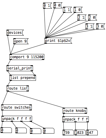
And here it is on the breadboard:
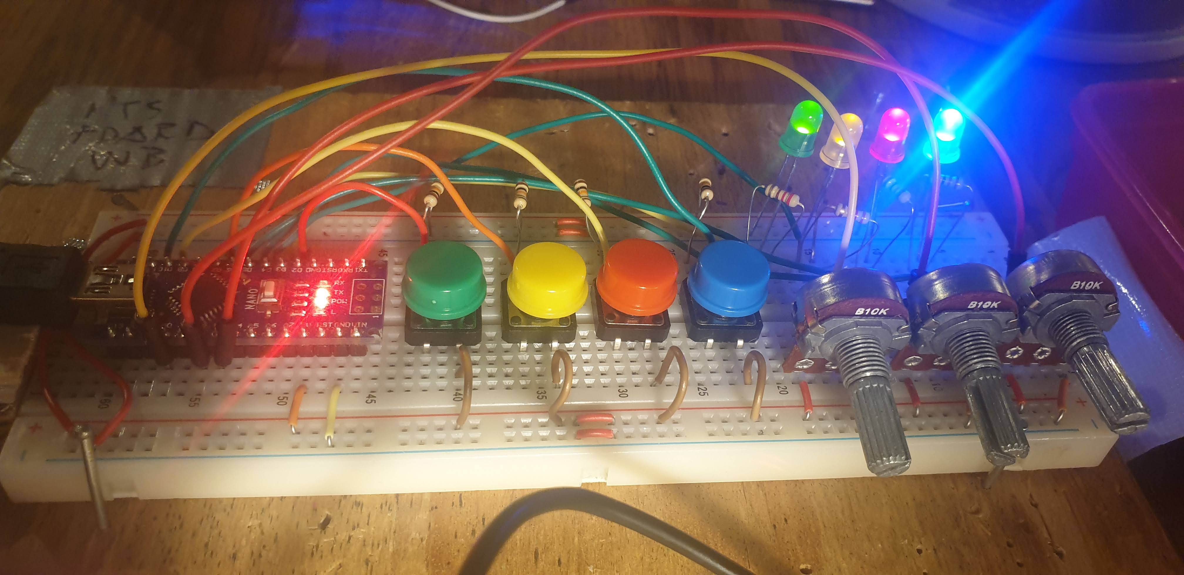
posted in I/O hardware diy
Having lots of switches into Pd
I would suggest to not mix the analog values with the digital ones. The first code could be changed to the following (using Serial.print() with the [serial_print] abstraction):
void setup()
{
  for(int i = 2; i < 14; i++)
  pinMode(i, INPUT);
  Serial.begin(115200); // perhaps use a faster baud rate
}

void loop()
{
  Serial.print("knobs"); // use "knobs" as a keyword so you can receive
  // the knob values as a list with a [r knobs] in Pd
  for(int i = 0; i < 6; i++){
    unsigned int knob = analogRead (i);
    Serial.print(" "); // first print a white space to separate the "knob" keyword from the values
    // and the values from each other
    Serial.print(knob); // then  print the actual knob value
  }
  Serial.println(); // finally print a newline character to denote end of data for keyword "knobs"

  // the same technique applies to the switches too
  // receive the switch values as a list with [r switches]
  Serial.print("switches");
  for(int i = 2; i < 14; i++) {
    int switchVal = digitalRead(i);
    Serial.print(" ");
    Serial.print(switchVal);
  }
  Serial.println();
}
As for writing to several outputs you need to set which output you want to write to and then the value you want to write. Here's an example that writes to several different digital outputs:
int pin = 0;
int val = 0;
// some random pins
int pins[4] = {3, 4, 5, 6];

void setup() {
  for (int i = 0; i < 4; i++) {
    pinMode(pins[i], OUTPUT);
    digitalWrite(pins[i], LOW);
  }

  Serial.begin(115200);
}

void loop() {
  if (Serial.available()) {
    static int temp;
    byte in = Serial.read();
    if (isDigit(in)) {
      temp = temp * 10 + in - '0';
    }
    else if (in == 'p') {
      pin = temp;
      temp = 0;
    }
    else if (in == 'v')  {
      val = temp;
      temp = 0;
      digitalWrite(pins[pin], val);
    }
}
With the code above you can send messages like this one print $1p$2v in Pd to the [comport] object. $1 is the number of the pin you want to light up starting from 0 and incrementing by 1 (so the first pin used which is pin 3 in the Arduino code would be 0 in the Pd patch), and $2 is the value, 0 or 1.
Note though that in the first code (and the code you posted), you're using all digital pins as inputs so there's no pin left to use as output. If you want to combine these two chunks of code you'll have to use less pins as inputs and leave some to be used as outputs.
 posted in I/O hardware diy
JASS, Just Another Synth...Sort-of, codename: Gemini (UPDATED: esp with midi fixes)
JASS, Just Another Synth...Sort-of, codename: Gemini (UPDATED TO V-1.0.1)
jass-v1.0.1( esp with midi fixes).zip
1.0.1-CHANGES:
- Fixed issues with midi routing, re the mode selector (mentioned below)
- Upgraded the midi mode "fetch" abstraction to be less granular
- Fix (for midi) so changing cc["14","15","16"] to "rnd" outputs a random wave (It has always done this for non-midi.)
- Added a midi-mode-tester.pd (connect PD's midi out to PD's midi in to use it)
- Upgrade: cc-56 and cc-58 can now change pbend-cc and mod-cc in all modes
- Update: the (this) readme
INFO: Values setting to 0 on initial cc changes is (given midi) to be expected.
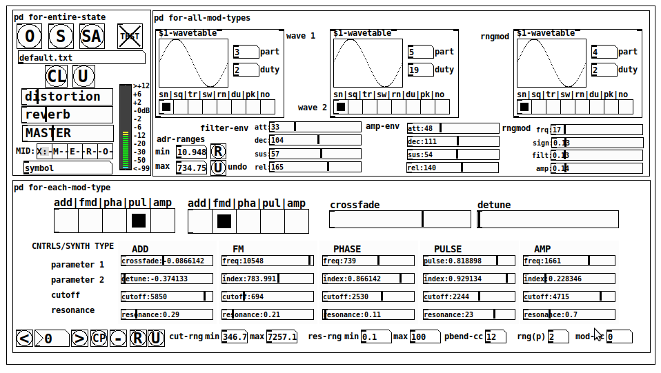
JASS is a clone-based, three wavetable, 16 voice polyphonic, Dual-channel synth.
With...
- The initial, two wavetables combined in 1 of 5 possible ways per channel and then adding those two channels. Example: additive+frequency modulation, phase+pulse-modulation, pulse-modulation+amplitude modulation, fm+fm, etc
- The third wavetable is a ring modulator, embedded inside each mod type
- 8 wave types, including a random with a settable number of partials and a square with a settable dutycycle
- A vcf~ filter embedded inside each modulation type
- The attack-decay-release, cutoff, and resonance ranges settable so they immediately and globally recalculate all relevant values
- Four parameters /mod type: p1,p2, cutoff, and resonance
- State-saving, at both the global level (wavetables, env, etc.), as well as, multiple "substates" of for-each-mod-type settings.
- Distortion, reverb
- Midiin, paying special attention to the use of 8-knob, usb, midi controllers (see below for details)
- zexy-limiters, for each channel, after the distortion, and just before dac~
Instructions
Requires: zexy
for-entire-state
- O: Open preset. "default.txt" is loaded by...default
- S: Save preset (all values incl. the multiple substates) (Note: I have Not included any presets, besides the default with 5 substates.)
- SA: Save as
- TEST: A sample player
- symbol: The filename of the currently loaded preset
- CL: Clear, sets all but a few values to 0
- U: Undo CL
- distortion,reverb,MASTER: operate on the total out, just before the limiter.
- MIDI (Each selection corresponds to a pgmin, 123,124,125,126,127, respectively, see below for more information)
- X: Default midi config, cc[1,7,8-64] available
- M: Modulators;cc[10-17] routed to ch1&ch2: p1,p2,cutoff,q controls
- E: Envelopes; cc[10-17] routed to filter- and amp-env controls
- R: Ranges; cc[10-17] routed to adr-min/max,cut-off min/max, resonance min/max, distortion, and reverb
- O: Other; cc[10-17] routed to rngmod controls, 3 wavetypes, and crossfade
- symbol: you may enter 8 cc#'s here to replace the default [10-17] from above to suit your midi-controller's knob configuration; these settings are saved to file upon entry
- vu: for total out to dac~
for-all-mod-types
- /wavetable
- graph: of the chosen wavetype
- part: partials, # of partials to use for the "rn" wavetype; the resulting, random sinesum is saved with the preset
- duty: dutycycle for the "du" wavetype
- type: sin | square | triangle | saw | random | duty | pink (pink-noise: a random sinesum with 128 partials, it is not saved with the preset) | noise (a random sinesum with 2051 partials, also not saved)
- filter-env: (self-explanatory)
- amp-env: (self-explanatory)
- rngmod: self-explanatory, except "sign" is to the modulated signal just before going into the vcf~
- adr-range: min,max[0-10000]; changing these values immediately recalculates all values for the filter- and amp-env's scaled to the new range
- R: randomizes all for-all-mod-types values, but excludes wavetype "noise"; rem: you must S or SA the preset to save the results
- U: Undoes R
for-each-mod-type
- mod-type-1: (In all cases, wavetable1 is the carrier and wavetable2 is the modulator); additive | frequency | phase | pulse | amplitude modulation
- mod-type-2: Same as above; mod-type-2 May be the same type as mod-type-1
- crossfade: Between ch1 and ch2
- detune: Applied to the midi pitch going into ch2
- for-each-clone-type controls:
- p1,p2: (self-explanatory)
- cutoff, resonance: (self-explanatory)
- navigation: Cycles through the saved substates of for-each-mod-type settings (note: they are lines on the end of a [text])
- CP: Copy the current settings, ie. add a line to the end of the [text] identical to the current substate
- -: Delete the current substate
- R: Randomize all (but only a few) substate settings
- U: Undo R
- cut-rng: min,max[0-20000] As adr-range above, this immediately recalculates all cutoff values
- res-rng: min,max[0-100], same as previously but for q
- pbend: cc,rng: the pitchwheel may be assigned to a control by setting this to a value >7 (see midi table below for possibilities); rng is in midi pitches (+/- the value you enter)
- mod-cc: the mod-wheel may be assigned to a control [7..64] by setting this value
midi-implementation
| name | --- | Description |
|---|---|---|
| sysex | not supported | |
| pgmin | 123,124,125,126,127; They set midi mode | |
| notein | 0-127 | |
| bendin | pbend-cc=7>pitchbend; otherwise to the cc# from below | |
| touch | not supported | |
| polytouch | not supported |
cc - basic (for all midi-configs)
| # | name | --- | desciption |
|---|---|---|---|
| 1 | mod-wheel | (assignable) | |
| 7 | volume | Master |
cc - "X" mode/pgmin=123
| cc | --- | parameter |
|---|---|---|
| 8 | wavetype1 | |
| 9 | partials 1 | |
| 10 | duty 1 | |
| 11 | wavetype2 | |
| 12 | partials 2 | |
| 13 | duty 2 | |
| 14 | wavetype3 | |
| 15 | partials 3 | |
| 16 | duty 3 | |
| 17 | filter-att | |
| 18 | filter-dec | |
| 19 | filter-sus | |
| 20 | filter-rel | |
| 21 | amp-att | |
| 22 | amp-dec | |
| 23 | amp-sus | |
| 24 | amp-rel | |
| 25 | rngmod-freq | |
| 26 | rngmod-sig | |
| 27 | rngmod-filt | |
| 28 | rngmod-amp | |
| 29 | distortion | |
| 30 | reverb | |
| 31 | master | |
| 32 | mod-type 1 | |
| 33 | mod-type 2 | |
| 34 | crossfade | |
| 35 | detune | |
| 36 | p1-1 | |
| 37 | p2-1 | |
| 38 | cutoff-1 | |
| 39 | q-1 | |
| 40 | p1-2 | |
| 41 | p2-2 | |
| 42 | cutoff-2 | |
| 43 | q-2 | |
| 44 | p1-3 | |
| 45 | p2-3 | |
| 46 | cutoff-3 | |
| 47 | q-3 | |
| 48 | p1-4 | |
| 49 | p2-4 | |
| 50 | cutoff-4 | |
| 51 | q-4 | |
| 52 | p1-5 | |
| 53 | p2-5 | |
| 54 | cutoff-5 | |
| 55 | q-5 | |
| 56 | pbend-cc | |
| 57 | pbend-rng | |
| 58 | mod-cc | |
| 59 | adr-rng-min | |
| 60 | adr-rng-max | |
| 61 | cut-rng-min | |
| 62 | cut-rng-max | |
| 63 | res-rng-min | |
| 64 | res-rng-max |
cc - Modes M, E, R, O
Jass is designed so that single knobs may be used for multiple purposes without reentering the previous value when you turn the knob, esp. as it pertains to, 8-knob controllers.
Thus, for instance, when in Mode M(pgm=124) your cc send the signals as listed below. When you switch modes, that knob will then change the values for That mode.
In order to do this, you must turn the knob until it hits the previously stored value for that mode-knob.
After hitting that previous value, it will begin to change the current value.
cc - Modes M, E, R, O assignments
Where [10..17] may be the midi cc #'s you enter in the MIDI symbol field (as mentioned above) aligned to your particular midi controller.
| cc# | --- | M/pgm=124 | --- | E/pgm=125 | --- | R/pgm=126 | --- | O/pgm=127 |
|---|---|---|---|---|---|---|---|---|
| 10 | ch1:p1 | filter-env:att | adr-rng-min | rngmod:freq | ||||
| 11 | ch1:p2 | filter-env:dec | adr-rng-max | rngmod:sig | ||||
| 12 | ch1:cutoff | filter-env:sus | cut-rng-min | rngmod:filter | ||||
| 13 | ch1:q | filter-env:re | cut-rng-max | rngmod:amp | ||||
| 14 | ch2:p1 | amp-env:att | res-rng-min | wavetype1 | ||||
| 15 | ch2:p2 | amp-env:dec | res-rng-max | wavetype2 | ||||
| 16 | ch2:cutoff | amp-env:sus | distortion | wavetype3 | ||||
| 17 | ch2:q | amp-env:rel | reverb | crossfade |
In closing
If you have anywhere close to as much fun (using, experimenting with, trying out, etc.) this patch, as I had making it, I will consider it a success.
For while an arduous learning curve (the first synth I ever built), it has been an Enormous pleasure to listen to as I worked on it. Getting better and better sounding at each pass.
Rather, than say to much, I will say this:
Enjoy. May it bring a smile to your face.
Peace through love of creating and sharing.
Sincerely,
Scott
 posted in patch~
Write to text file.
3 years ago... but still usefull.
I wanted to write a file similar to yours, to be imported into a spreadsheet software, as CSV (Comma Separated Values). [textfile] store in space-separated-values with return-carriage (or semicolon/return-carriage) data separator.
LibreOffice can import CSV with tab or comma or semicolon or space (or any other) values separator. I don't know about MS-Excel.
Did you get what you needed?
 posted in technical issues
Converting 0-127 CC Knob Into "Endless" Encoder
Whew... that's a tricky one that I myself have attempted before. There are a few ways to potentially do this, but it depends on some things... Like nodsp said, the range is an important factor as well as the behavior of how it handles jumping between maximum and minimum values... and also the knob that is being used along with how the device handles sending the values received for that knob. If it spins endlessly, but stops sending values after after the knob turns past the minimum or maximum, thats a problem. If the knob reaches the min or max, and continues to send the min or max value each time the knob is turned past the value, then i'd do an endless encoder like this...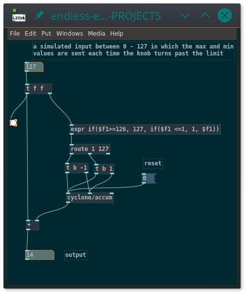 endless-encoder.pd
To make a range constraint, just throw a modulo ( [%] ) object at the output, or something like [cyclone/wrap]
If the device being input does not send values once the knob goes past the limit, it becomes a bit more complicated. Youd have to take the expr object and set it so that when it receives a 0, it outputs 1 and if it receives a 127, it outputs 126, then route that back into the device to set the value so that you will get an output from the device on the next turn of the knob. does that make sense?
 posted in technical issues
New knob GUI object
Hi Pd
Here is a higher precision & functions knob GUI object [abcknob], as a replacement for [knob].
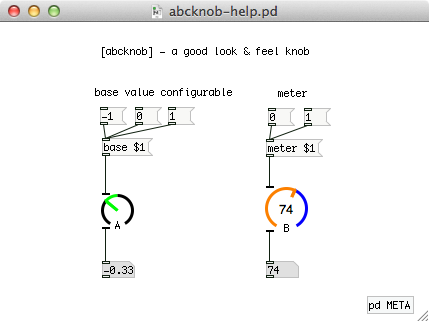
Main features (advantages over the wellknown [knob]) :
- A variable gauge startpoint, not only leftmost but also any point you can set
- Available a numerical meter at the center area of the knob
- Accurately showing knob direction when its degree is 90, 180 or 270
- Downward compatibility for [knob]; Your patch will work well if you replace [knob] with [abcknob] by any text editor
I made this object when the pd-extended was on-going.
Recently I found that the pd-extended is now outdated and the current pd-vanilla does not supply the [knob] object. So I updated my own object and would like to share it to help your patching life.
abcknob - Mac, Win and Linux binaries archive for Pd 0.47
Yoichi
 posted in extra~
Dynamic Effect/Plugin Loader esp. For Rapsberry PI (DIY2 and Stamp Album effects/plugins)
Dynamic Effect Plugin Loader esp. For Rapsberry PI (DIY2 and Stamp Album effects/plugins)
DynamicEffectPluginLoaderForPI.zip
Background:
In the last couple of days I finally built something I have needed and wanted for a while (which later on I will discuss in more detail under a separate thread): an Arduino electric guitar.
In other words, I took the connections off the 5-way and knobs (internally connected to the pickups and line out) and rerouted the switch and knobs to an arduino. The reasoning being I can control Way more with pd and those knobs than what they were originally intended to do if I capture their output using Arduino.
However, the patch I had built for it was clocking in at about 275-300% of the pi's cpu. And while I could have gone back and added switches (which I took out a while back, to replace with fade-mixers for when I change an effect) throughout, the thought of doing that was more daunting than (considering how elaborate the patch is) I wanted to undertake.
Enter: Dynamic Patching.
I found that with just 3 straight-chained effects the pi ran at only about 10%.
So...here's what I built and am sharing now (before tying it into the arduino guitar, because I think others might want to go ahead and learn from it, extend it, expand upon it, use it, etc. etc.).
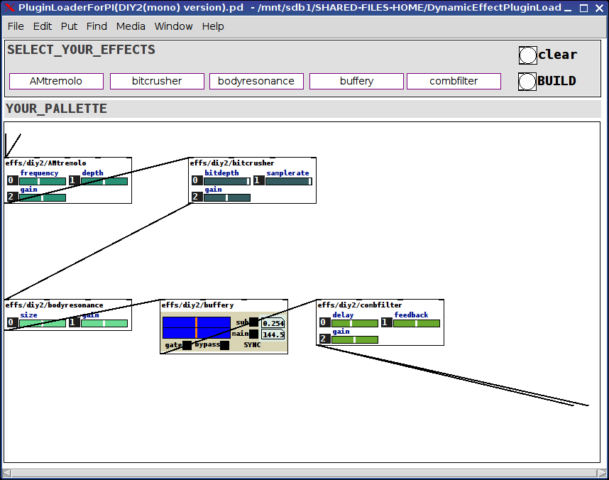
The patch(es, there are two, one laid out for the DIY2 plugins and one laid out for the Stamp Album ones, will probably consolidate them later, but other things are demanding my attention) is pretty straight forward:
(Dependency on the tof/menubutton, tof can be found via deken)
Click on the menus at the top to select an effect for each of the 5 slots or select the "unchanged" effect to leave that slot open.
Then click the BUILD bang or the CLEAR bang (to start over).
The selected effects will load into the PALLETTE subpatch already connected to adc~ and dac~.
That's really about all there is to it. Very straight-forward, clean, and very cpu light-weight. The racks of all 5 slots I tested ran at about 10-12% on my PI 3r2.
Hope you can make use of it. And would love to hear feedback.
For the future:
Add a hid-stomp controller to load preset racks (which you can send in via the tof/menubotton) to load racks on the fly;
Add a meta-level to send either hid, osc, or arduino commands to each of the loaded effects.
Merry Music to us, one and all.
Peace,
Scott
p.s. Oh! The arduino guitar: though it has no connected pickups it gets its audio signal from an (about) 1" piezo mic fun-tacked to the knob-well inside the guitar. Sounds great. Just pure guitar. The tone, texture, etc. come after the fact via the pd-side.
Ciao for now.
Wanna say: the real genius lies not in what I cobbled together, but the strength of will and purpose it took for the two original developers to make abstractions so completely consistent and thoroughly aligned. My highest regards to you both. Thank you, both, so very much, for helping to make my "job" so easy.
posted in patch~