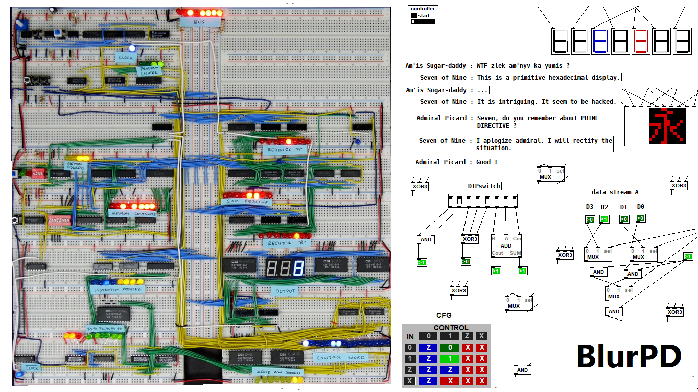
BlurPD - digital logic framework system for Pure Data [v3]
BlurPD is a framework system to extend Pure Data with the ability to make
digital logic circuits while taking advantage of the DSP capabilities of Pure Data. In order to design and simulate interesting circuits, ASIC chips, DSP processors or entire CPU's, all in Pure Data. It is made from jucy fundamental modules (Lego blocks) that when put together turn Pure Data into a madness of bits ...
Bug Fixes & Notes [v3]
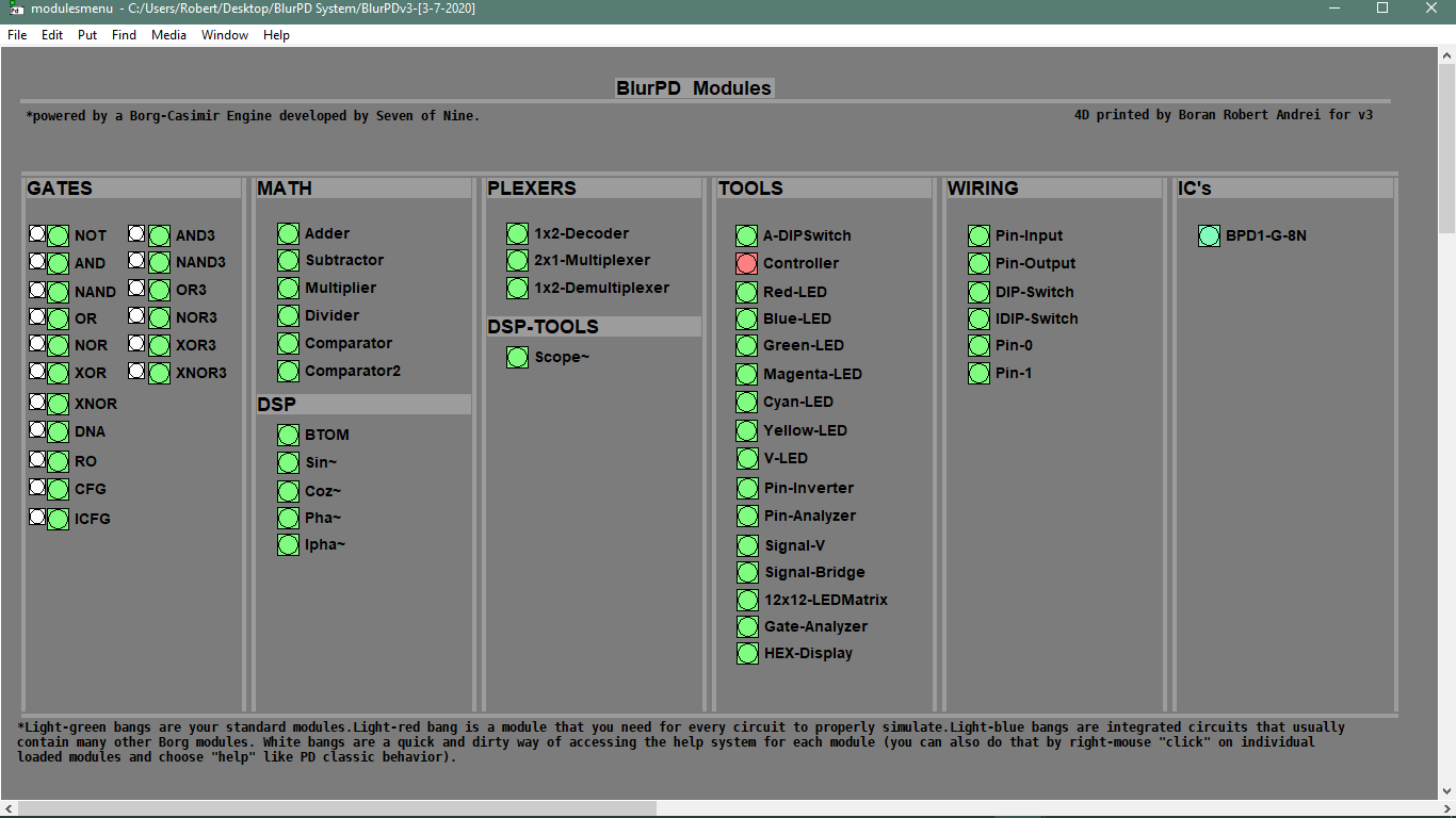
Modules [v3]
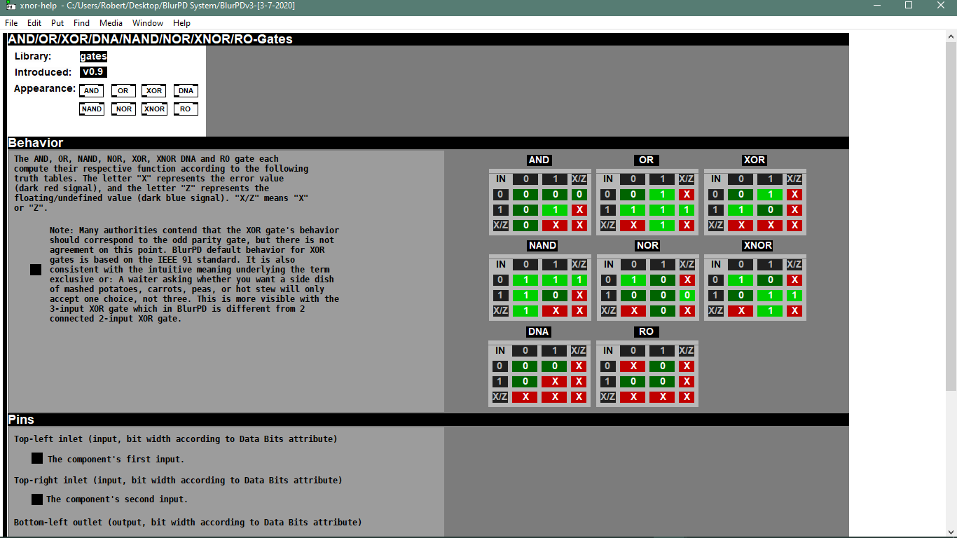
- GATES : not,and,nand,or,nor,xor,xnor,cfg,icfg,dna,ro,and3,or3,nand3,nor3,xor3,xnor3
- PLEXERS : 2x1multiplexer,1x2demultiplexer,1x2decoder
- MATH : adder,subtractor,multiplier,divider,comparator,comparator2
- IC : bpd1g8n (integrated 8xNAND gates)
- TOOLS : redled,blueled,greenled,yellowled,magentaled,cyanled,sigv,pininv,gateanalyer
ledmatrix,controller,adipswitch,vled,hexdisplay,sigbridge,pinanalyzer - WIRING : pininput,pinoutput,pin0,pin1,dipswitch,idipswitch
- MODULES : the core library for BlurPD built-in modules
- ICMODULES : the core library for "IC" modules
- DSP : btom,sin~,pha~,ipha~,cos~
- DSPTOOLS : scope~
New Stuff [v3]
- Changes to the Help system. Better GUI and integration [v3]
 patch download
BlurPDv3-[3-7-2020].zip
 BlurPD archive (older versions)
BlurPDv2.9-[3-3-2020].zip
BlurPDv2.8-[3-3-2020].zip
BlurPDv2.7-[3-3-2020].zip
BlurPDv2.6-[3-1-2020].zip
BlurPDv2.5-[2-29-2020].zip
BlurPDv2.4-[2-27-2020].zip
BlurPDv2.3-[2-26-2020].zip
BlurPDv2.2-[2-25-2020].zip
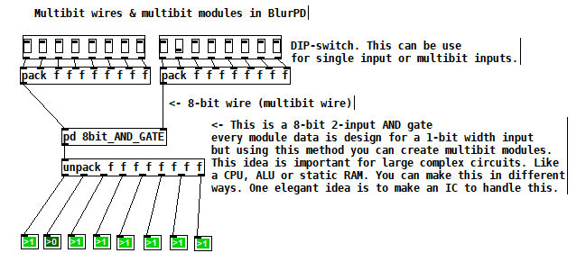
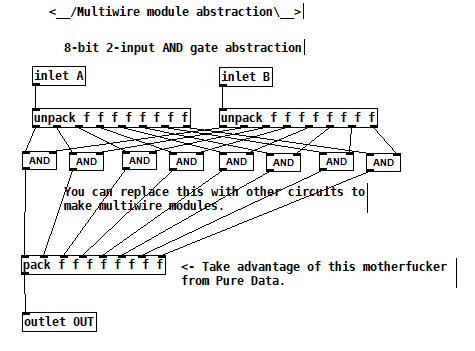
Multibit modules for more complex circuits [v3]
4-bit Boran-Tsung function using a 4-bit ALU (arithmetic logic unit) circuit made with BlurPD [v3]
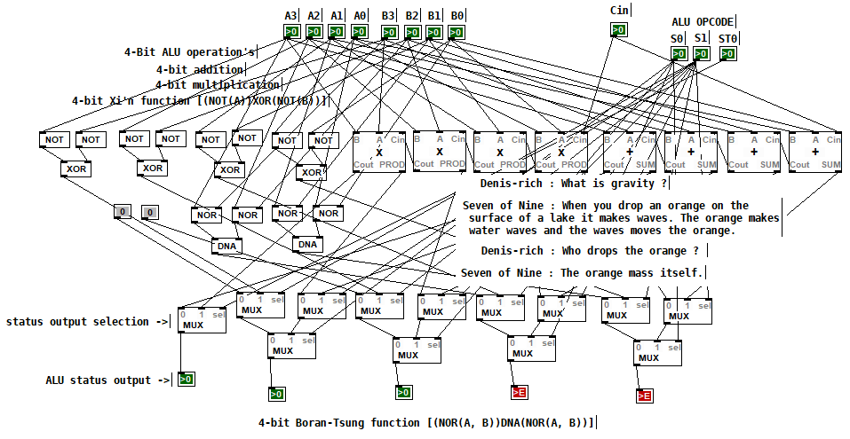
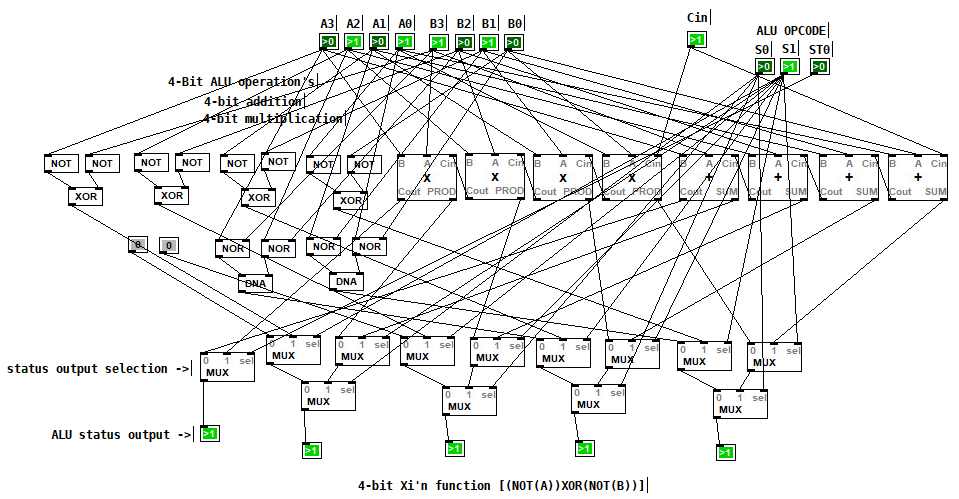
4-bit Xi'n function using a 4-bit ALU circuit made with BlurPD [v3]
Snapshot of the modules system and help system [v3]
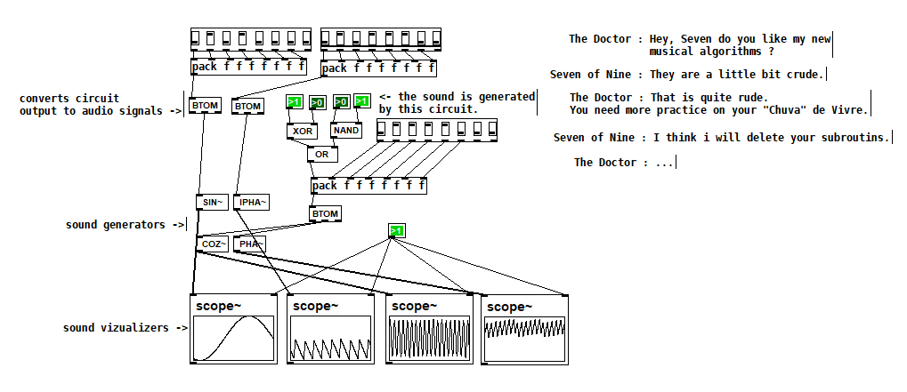
Making generative sounds using new DSP modules [v2.9]
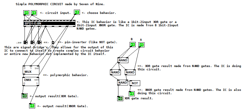
Polymorphic circuit [v2.7]
Application 1 of BlurPD system from [v2.3]
Application 2 of BlurPD system from [v2.3]
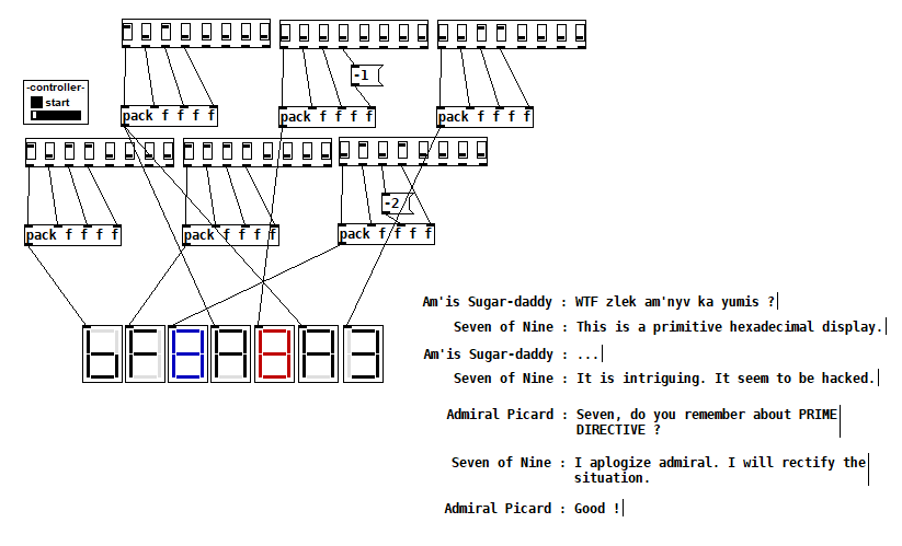
Hexadecimal display [v2.3]
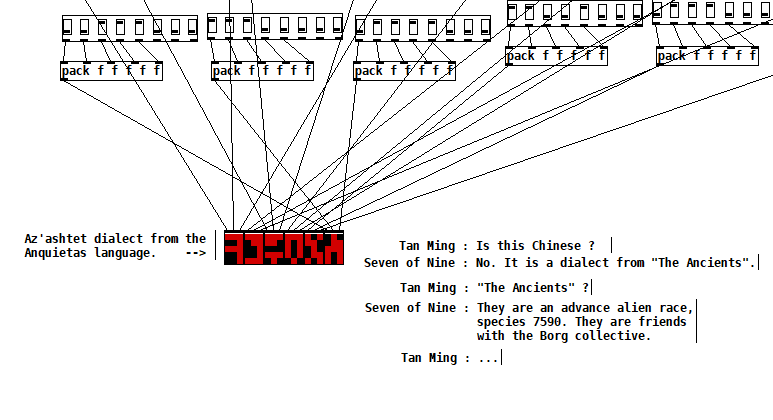
The Ancients [v2.2]
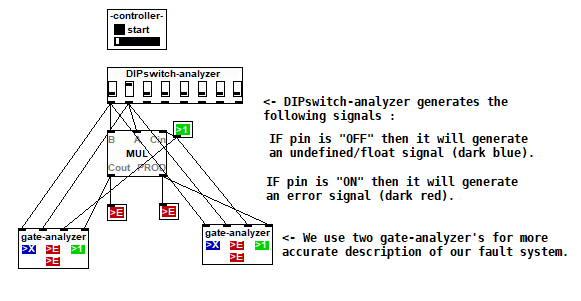
Complex analysis using a DIP-switch analyzer [v2.1]
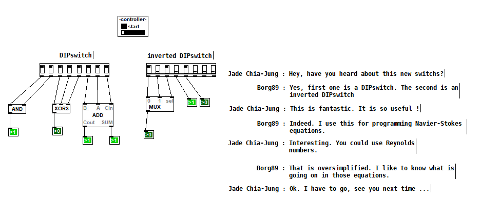
DIPSwitch from [v2.0]
 posted in patch~
Assistance with select function needed...
@Ikeobob I don't know why an "is it equal" test fails with fast changing floats even when the value is printed numerous times.
Someone clever will tell us...... @jancsika
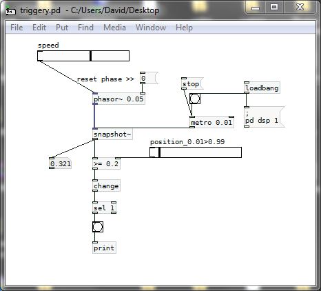
A "greater than" or "less than" test will work, and the [change] object will force the test to trigger only once....... but only on the rising part of the [osc~] curve with a "greater or equal" test.
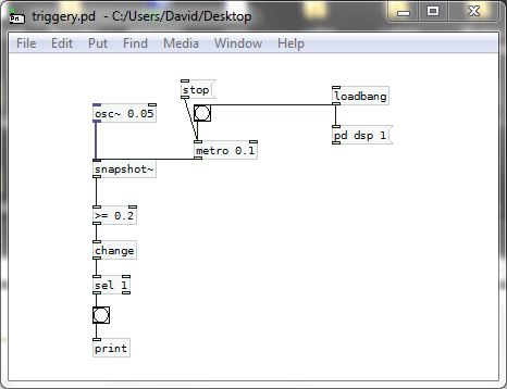
SO....  .... that gets complicated as for a trigger on other parts of the curve a different test would be needed.
The other problem you will have with [osc~] for this application is that a sine wave is not giving you a linear output.... so for timing purposes you are lost.....
You should use a sawtooth wave instead........ so [phasor~] is a better friend than [osc~]...... and as there are only positive values the test can stay the same. You are simply choosing a point on the ramp, and it is linear......
triggery.pd
And then you could be better off using [line] to trigger as the cpu use should be less.
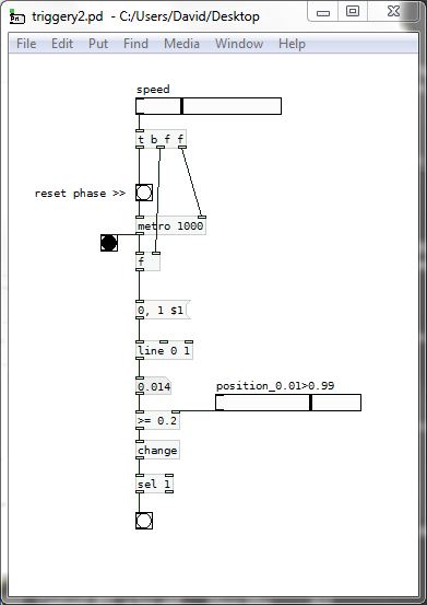
AND...... much better.......
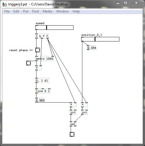
If we scale up the "equals" test to integers then we can test from zero to one and [select] works.......
It should also work with the [phasor~] example above...... BUT..... with [phasor~] you would have to scale in a way that makes sure that a match occurs and that you do not get more than one trigger per cycle.
triggery3.pd
David.
 posted in technical issues
Add a new line to [textfile]. How?
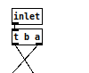
@RetroMaximus Trigger is used to control the order of operations.
This is not good practice:
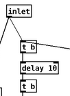
This is better:
Not good:
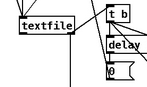
Better:
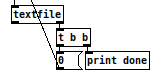
Not good:
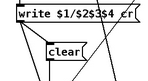
Better:
")
 posted in technical issues
Tabwrite~/array has problems working as a long timebase oscilloscope?
Hi @whale-av ,
Many thanks for the feedback!
First, a note - I also checked [Scope~] found in pd-extended (pd-l2ork, Purr-data) - and it has also its troubles:
- It only reacts on zero-crossings - so it basically shows phasor~ as a straight line, unless it is brought down [-~ 0.5] a bit;
- If using bufsize 1000, it basically updates more than each second - so buffer size seems not to be expressed in samples ?!
Maybe it's possible to control this somehow, since if I open a patch with [Scope~] in PD vanilla, I do get some numbers:
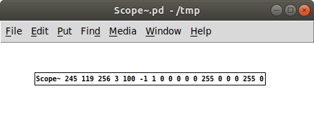
... but I cannot find documentation on this anywhere, and don't really have the time to reverse engineer it...
@whale-av said:
@sdaau_ml Reliable will be to put the data and then bang once only for the new data.
scop.pd
Well, I don't think this will help me much:

First, the timing of slider bangs is inconsistent, at least on Linux/Gnome (and possibly macOS) - sometimes it will hit at 30-40 ms apart, sometimes in much less than a millisecond ( see https://forum.pdpatchrepo.info/topic/8961/repost-measuring-the-elapsed-time-for-gui-hsl-slider-object-events-in-puredata ); and that means sometimes I'll get more data shown in the array98 graphs, and sometimes less (which is not how an oscilloscope display works)... Also, it will not be continually updated, as you noted:
@whale-av said:
Unless you want continuous update in which case you need [snapshot~] and a counter..... sort of like this....... phase meter.zip
Ok, this is pretty cool, thanks for that:
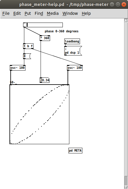
... but this gives me Lissajous curves, not time-domain waveform which I need. Although, I guess [snapshot~] will "lose" some data (due to artifacts of a sampling process), whereas I'd prefer to throw data directly in the array...
@whale-av said:
This might help......... scop2.zip
You will need to play around with the metro timing and the length of the array (and therefore the count object....... send the length of the array to it's right inlet so that it counts through the whole index), doing some range sensing (trigger) math just like a real scope if you want to auto stabilise the waveform.
{{note.... this is using [tabwrite]...... not [tabwrite~].......}}
Ah, this is pretty cool - and actually seems to work close to what I want:
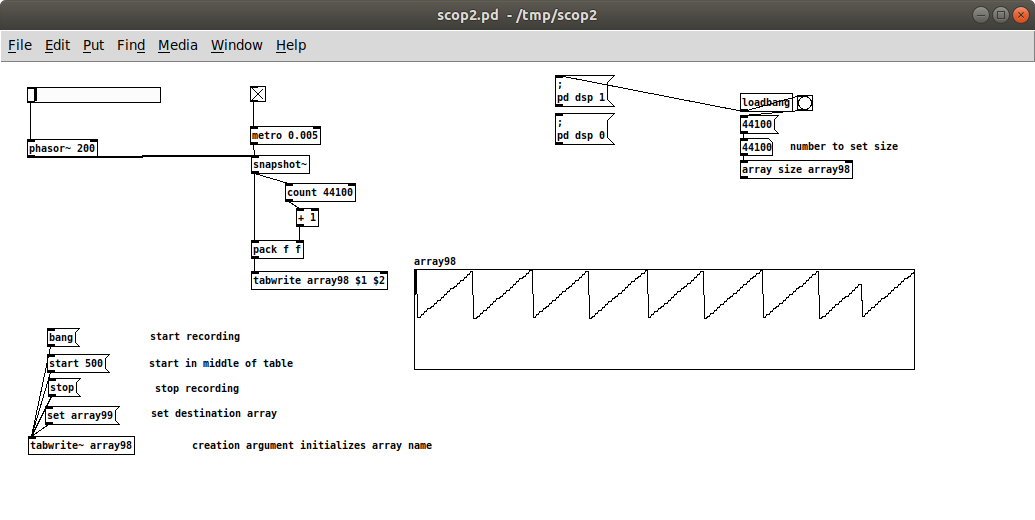
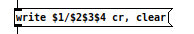
So, I guess [tabwrite ___ $1 $2] means write value $1 at index $2 (couldn't find anything explicit about this syntax in the help file)? In any case, even if it eats quite a bit of CPU, it seems to do the trick for what I need (and thankfully, I don't really need trigger conditions right now)..
Many thanks again for the help,
Cheers!
 posted in technical issues
MobMuPlat OSC-to-MIDI Remote Control, spec. for PD, Guitarix, and Rakarrack and other guitar effects apps
It's always funny to me how working on one PD project results in fruit that might also prove useful.
Currently, working on a broader project, but this part (at least) (I think) is ready for distribution.
Background: I Really hate leaving the side of my guitar (for example to click a mouse or tweak a setting) when I am playing. So designed this mmp app so that I can attach (with funtack, ex.) my handheld to my guitar and control my settings from there or perhaps even as I play. Like so:
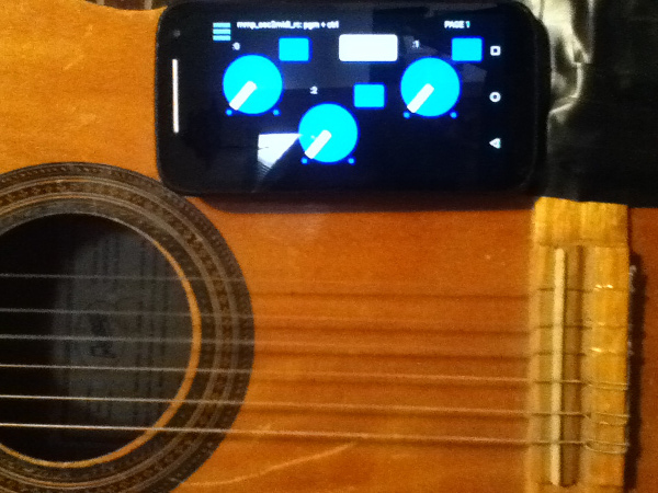
[Aside: the broader project also includes (on the front-side of the app) controls driven by the handheld's tilt, as well as, the adc~ pitch, env~, and distance of the pitch from a "center". But that part has to wait (though the code is all inside the mmp_osc2midi_rc.pd patch just disconnected/does not use the cpu).]
SETUP (linux is what I know, so other OSes may work just can't/haven't tested them):
JACK
Pure Data
a2jmidid - JACK MIDI daemon for ALSA MIDI (in the Ubuntu at least repos)
guitarix a/o rakarrack, or other midi-driven effects apps (such as the included set of 30 pd effects(see below))
PIECES:
The mmp_osc2midi_rc.zip (extract(android)/install(ios) to MobMuPlat directory)
The osc2midi_bridge.zip (to be run on the "pd receiver") and includes the osc2midi_bridge.pd, help file, and a set of 30 mmp-ready-(mono) effects (in the ./effs directory) that can be used if PD is to be used as the receiver. (They are standardized to include 3 inlets: left=inlet~, center=[0 $1(, [1 $1(, [2 $1( messages sent to 3 parameters on the effect, and right=[switch~] and 1 outlet~ and a demo guitarix "bank" file called "MIDITEST.gx" (which includes 2 presets/programs and set midi values (0-8) to test. Just add the file to the guitarix config "banks" folder).
Instructions:
- Start Jack;
- In Pure Data, open the osc2midi_bridge-help.pd file; toggle "listen" on; and set MEDIA to "ALSA-MIDI" (the additional pieces are just examples of receiving the midi values);
- In Jack>ALSA: Connect Read:MIDI to Write:PD & Read:PD to Write:Midi;
- From the command line execute "a2j_control start" (no quotes);
- Start (ex.) guitarix;
- In Jack>Midi connect a2j:Pure Data(capture) to (ex) gx_head_amp:midi_in_1.
Note/Alert/etc. For a machine to receive OSC messages the recipient-computer's firewall must (I believe) be turned off.
GUI:
The GUI has 3 pages that look (basically) as follows (with the subsequent 2 pages having only the 3 knobs and 3 buttons).
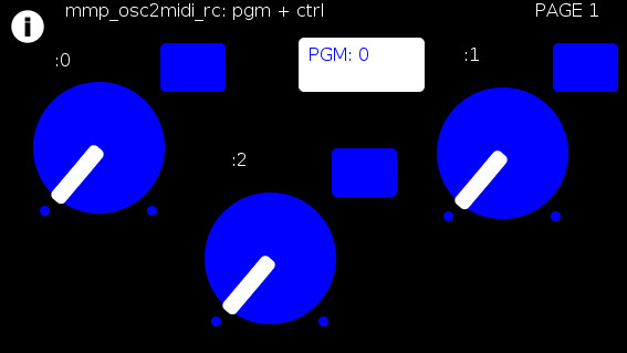
The buttons trigger text entry boxes which allow you to enter numbers (0-127) representing:
PGM: the number sent to (midi) [pgm]
and
(the buttons beside the knobs) the midi value, i.e [ctrl] (0-127), each knob is to be sent to (all on channel=0). (The resulting number of which are all written to the label to the left.)
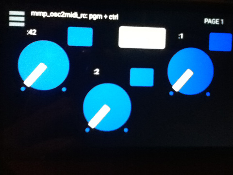
For example:
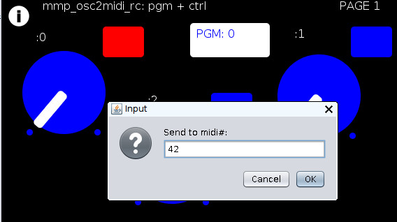
Results in:
You can now to do 1 of 2 things:
Set the mmp-knobs to whatever midi values you have set in guitarix
or
Set the guitarix midi values (mousewheel click on a control) to one of the mmp preset 0-8 midi values.
WOW!!!
That took a helluva a lot of writing (and reading) but I hope you can both see the value and make use of this bit of technology.
As I said before,
I look forward to being able to fine tune my sound ALL while my hands and I are BOTH still at my guitar and not bend over, move, etc. etc. etc. to get the sound I want.
Peace, Love, and Ever-Lasting Good Cheer.
If you made it this far ") , Thanks for Listening.
, Thanks for Listening.
Sincerely and Optimistically,
Scott
p.s. ask whatever you want regarding setup, how to use, points-of-clarification, etc. I am more than happy to help.
"Out of Love comes Joy"
 posted in patch~
Build a MIDI controller with the Arduino, Firmata and Pure Data
Time to start contributing some knowledge back to the wonderful world that is the internet; today, a step by step nice and easy tutorial on getting started to building your own MIDI controllers with the arduino.
When researching for my ableton controller project, I didn’t find much out there about using firmata on an arduino to send data to software. The standard approach just seemed to be create the code in the arduino language, upload it to your board and hack one of those MIDI to USB cables as a bodge job way of getting the MIDI out of the arduino.
So why firmata and pure data? Well the whole idea of firmata is that you flash it to your arduino, and it throws out serial about whats going on with the arduino inputs and outputs, then you decide how the software treats the readings coming in and going out.
Theory out the way, lets build some controllers. You’ll need a few things…
HARDWARE:
An arduino and something to wire into it (for this i’ll be using a pot)
A USB cable for your arduino
SOFTWARE:
Arduino – http://arduino.cc/en/Main/Software
Pure Data – http://puredata.info/downloads
Firmata – http://at.or.at/hans/pd/objects.html#pduino
Something to patch your new controller into; like Reason or Ableton Live
- SETTING UP FIRMATA AND PURE DATA
Install Pure Data and create a folder to store all your patches somewhere. Unzip Firmata and add the files ‘arduino.pd’, ‘arduino-test.pd’ and ‘arduino-help.pd’ to your new Pure Data folder. The ‘arduino.pd’ file is the object that we use in PD for opening up communication with your arduino and routing it to PD. Done? Awesome, your software is almost set up.
- FLASHING FIRMATA TO YOUR ARDUINO
Install the latest version of arduino and open it up. Connect your arduino with the USB cable to your laptop (i’m using a macbook for this by the way). In the example patches, open up “Standard Firmata”, select your board (im using an arduino mega), and your serial port (look for tty.usbserial for use with a USB cable). Then compile and hit the upload button and your arduino is now ready to use firmata and communicate with Pure Data!
- WIRING UP A POT
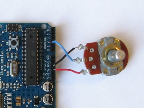
Potentiometers are cool, and theres a great arduino tutorial of how to wire one up here: http://www.arduino.cc/en/Tutorial/Potentiometer
Basically, all you need to know is that there are three pins; your two outer pins govern voltage flow across the pot, meaning one has to be 5V and the other has to be ground. It doesn’t matter which, but your 5v pin is going to be where your pot reads maximum, so convention dictates this should be the right hand pin. The center pin needs to be connected to an analog in on the arduino and will read the value of the pot as it sweeps from ground (0v) to 5v.
All wired up? Plug it into your laptop and open Pure Data, we’re ready to get things talking.
- SETTING UP OUR PATCH
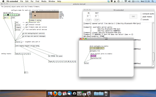
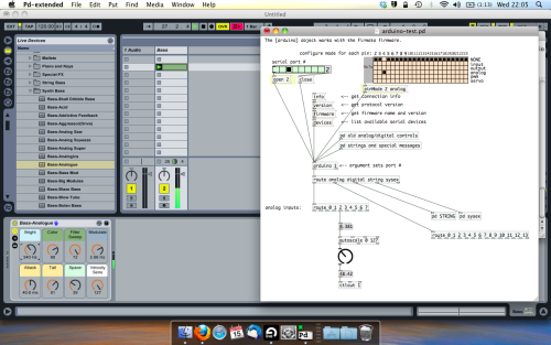
Open the example “arduino-test.pd” Pure Data patch you copied over earlier. It should look like this one…
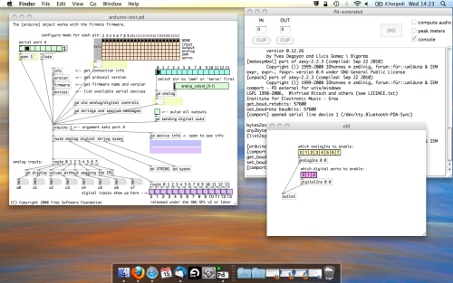
The test patch has everything we need to open a connection and enable pins. Firstly, lets delete a bunch of stuff and make our window a bit bigger. Hit Command + E to enter edit mode in Pure Data.
Ok a quick explaination; the key component here is the ‘arduino’ object. This is being drawn from the file you copied in earlier, and is what communicated with your arduino. Here we can do everything to control the arduino from opening a connection, to receiving data.
The large grid allows us to set the mode of each pin on the arduino. Remember pins 0 and 1 are reserved for Rx and Tx. I’m using analog pin 4 for this demo, so I’ve set my pin mode for pin 4 to ‘analog’.
Now we can plug our arduino in and get a reading from the potentiometer.
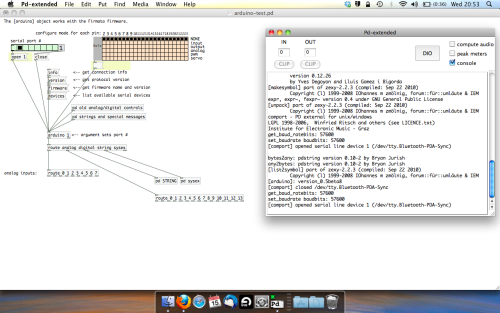
- ARDUINO INTO PURE DATA
With your arduino plugged in, hit command and E to bring us out of edit mode. In our patch, click on ‘Devices’ above the arduino object and open up the pure data terminal. (That other thing that loads with PD that has all the scary code in)
The “Devices” message connected to the arduino object pings your computer to find what devices are connected and on what serial ports. Since we’re using a USB cable to connect our arduino, we’re looking for something with ‘usbserial’ in it, in this case; port 2.
Select the relevent port in the green box at the top (remember the first box is ‘0’, second is ‘1’ and so forth) and hit ‘Open’ to establish a connection. Check the terminal to see if the connection was sucessful.

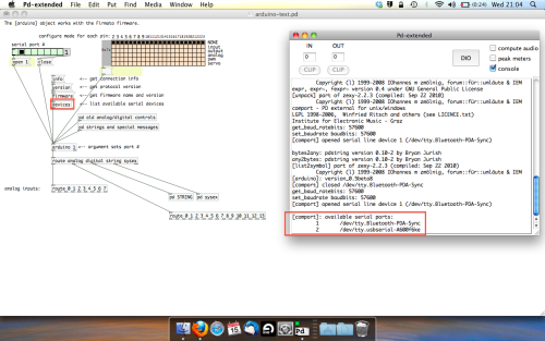
Now lets check we’re getting something in. Create a number box (Command + 3) and connect it to the relevent pin on the ‘Route analog’ box at the bottom. In this case, pin 4.
One more thing; if you’re not getting any readings in, you’ll need to click on ‘pd old analog/digital controls’ and enable your pins here too. What I tend to do in my patches is just not include the large grid but make my own ‘old pd’ controls custom to what i’m enabling/disabling to save space.
Here’s what the ‘old analog/digital controls’ subpatch looks like (pin 4 enabled)…
Come out of edit mode and check that you’ve got readings. If so congratulations! If not, troubleshoot, start with making sure your usb connection is opened, make sure all the correct pins are enabled (remember you’re counting from 0 not 1 on most of these buttons in PD, it’s just the way computers work).
- SCALING READINGS TO MIDI
So we’ve got a reading and chances are it’s to 3 decimal places between 0 to 1. No problem, create a new object (Command + 1) and type “autoscale 0 127”. This allows us to scale the input to a min and max value, in this case 0 to 127 of MIDI. Next, lets get things looking nice, create a new object and type “knob”. Connect this AFTER the autoscale object. (the knob is default set to read inputs from 0 to 127. Then create another number to display the scaled MIDI data coming out, and finally a new object and type “ctlout 1”.
It should look something like this…
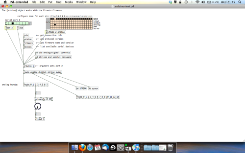
The second box should be outputing values from 0 – 127 now, and the knob giving a visual representation of your potentiometer.
Now lets patch it into ableton…
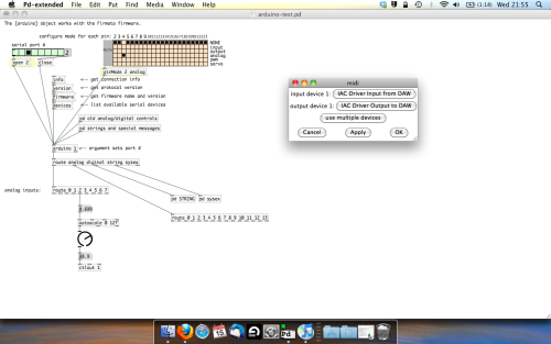
- PURE DATA TO ABLETON LIVE
Firstly, you’ll need to set up your macs IAC driver if you’ve not done this. Basically you’ll need to go into Audio/MIDI preferences and enable your IAC driver. Then create a new input and output. One for input to DAW and one for output from DAW. Google around for a tutorial on this, its really simple, a 30 second job.
After you’ve set up your IAC driver, go back to PD and go to preferences > MIDI Settings, and connect your IAC driver.
Open ableton and go to its MIDI preferences. Create a device listing for your IAC driver and enable its ins and outs into ableton like so…
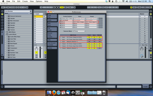
And thats it! Create an instrument and try to assign something! I’ve got it controlling the brightness of a bass sound here.
Shout out for Facu who requested this tutorial. Hopefully it’ll help some of you looking to get into this stuff and start building things but with no idea where to start.
 posted in tutorials
Unexpected noises appear when playing score
@whale-av so to finally record ill use this folder,,,, I already have all the voice gen up to 31... just need the part where the harmonics are faded out, for the next score i will start to implement all that you have given me,...1_vod_6.pd mix_mod.pd part_timbre.pd part_voice.pd voice_gen1.pd voice_gen2.pd voice_gen3.pd voice_gen4.pd voice_gen5.pd voice_gen6.pd voice_gen7.pd voice_gen8.pd voice_gen9.pd voice_gen10.pd voice_gen11.pd voice_gen12.pd voice_gen13.pd voice_gen14.pd voice_gen15.pd voice_gen16.pd voice_gen17.pd voice_gen18.pd voice_gen19.pd voice_gen20.pd voice_gen21.pd voice_gen22.pd voice_gen23.pd voice_gen24.pd voice_gen25.pd voice_gen26.pd voice_gen27.pd voice_gen28.pd voice_gen29.pd voice_gen30.pd voice_gen31.pd
 posted in technical issues
Drag-queen sequencer
Hi ,
I made this midi sequencer that allows you to create and modify notes on a piano-roll using keyboard and mouse.
I was not familiar with data structures but i came accross and recycled a drag-n-drop patch by lzr:
https://forum.pdpatchrepo.info/topic/9336/drag-n-drop-example
Maybe someone can help me with note deletion: is there a simple way to delete a scalar?
What I did for now is keeping track of pointers in a [coll].I can delete one selected note from the coll and reload everything.
I'm sure there's something easier to delete a pointer...
The patch needs a nice piano-roll design and has a few bugs ..
Tell me if it works ok for you,
Cheers,
Paulinho
drag-queen-sequencer.2.pd
1-save.txt
2-save.txt
map2.pd limit-help.pd limit.dll
Edit: added save and load system, and note creation with lists
Edit2: added map2 object
Edit3!: added limit object from maxlib library
 posted in patch~
Maximo (Guitar Rack) - 6 slots with 1 of 60 effects per slot (using "abs_effects_router" + an OSC controller (MobMuPlat)
Maximo (Guitar Rack) - 6 slots with 1 of 60 effects per slot (using "abs_effects_router" + an OSC controller (MobMuPlat)
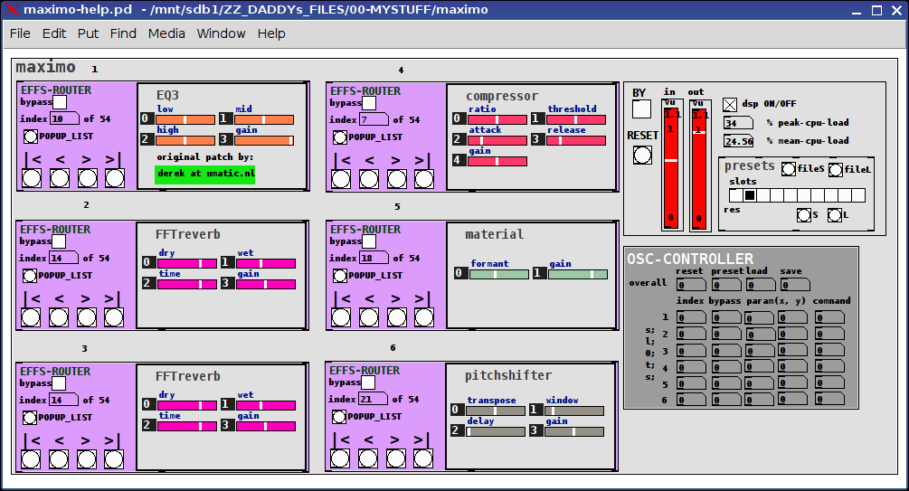
The app is "maximo-help.pd".
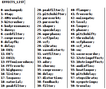
maximo is an effects-chain giving the user 6 slots each one of which may be used to select from 1 of 60 effects (the first being "unchanged").
Check her for details about how to use the "abs_effects_router", http://forum.pdpatchrepo.info/topic/10693/abs_effects_router-60-effects-in-one-abstraction-router-from-diy2-stamp-album-my-abs/1 .
It also includes
- a "maximo/admin.pd" abstraction to control:
dsp, bypass (all), reset (to set all effects to "unchanged"), and 9 presets (0 reserved for program usage) and both save-to-file and load-from-file preset buttons
- an Open Sound Control (OSC) mapper ("maximo/osc_control.pd") for sending values (0 thru 1) to controls /cc/1 thru /cc/34 (see the patch for details).
and
- an example OSC (MobMuPlat) controller at "./maximo-osc.mmp" and "./maximo-osc-mmp.pd"
MAXIMO EXAMPLE
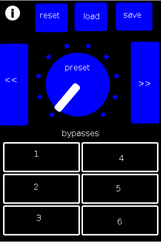
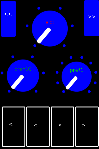
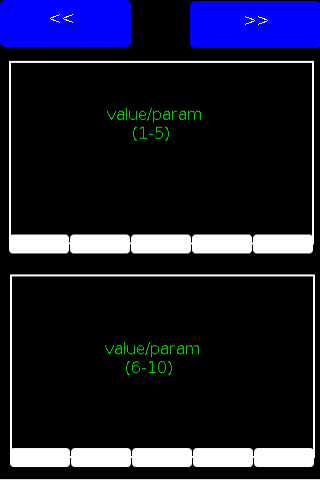
MOBMUPLAT INTERFACE
PAGE 1
PAGE 2
PAGE 3
All of this was contingent on the foundation and resources laid out in the DIY2 and Stamp Album collections and actually this was largely an example of persistence not any real insight and the largest percentage of the success goes to their creators for being so diligent about standardizing their abstractions.
I DO however hope you find it useful.
My GOAL was to eliminate what is often the case with effect stacks (I have seen) of having to connect all the effects. This eliminates that and makes it much cleaner: only having to select from the (tof/pmenu POPUP_LIST button) or navigate to the desired effect with the standard "first, previous, next, last" controls.
I hope you find the work useful and capable of helping you to manifest all those wonderful sounds you have in your head.
Peace and only Love,
Scott
The List of Effects per slot is:
posted in patch~
curious: [clone] in sequence instead of sum
I just realized that it is a bit different in the audio world. I haven't used the audio objects yet.
Here, the signal is send to the clone with the highest ID first:
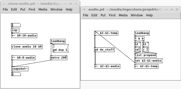
clone-audio.pd
audio.pd
Here is one version with throw~/catch~, which might be more convenient:
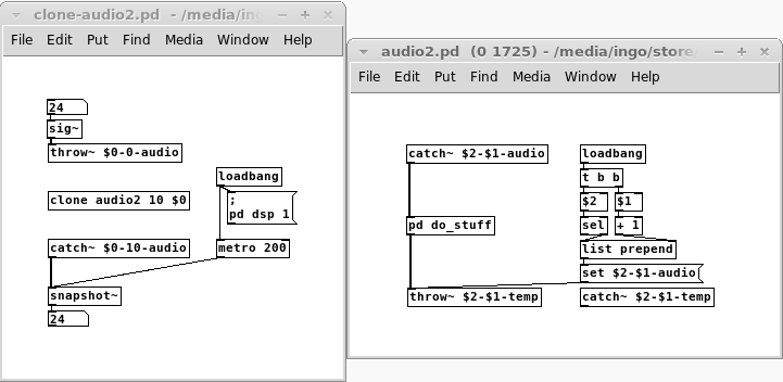
clone-audio2.pd
audio2.pd
posted in technical issues