Ganymede: an 8-track, semi-automatic samples-looper and percussion instrument based on modulus instead of metro
Ganymede.7z (includes its own limited set of samples)
Background:
Ganymede was created to test a bet I made with myself:
that I could boil down drum sequencing to a single knob (i.e. instead of writing a pattern).
As far as I am concerned, I won the bet.
The trick is...
Instead of using a knob to turn, for example, up or down a metro, you use it to turn up or down the modulus of a counter, ie. counter[1..16]>[mod X]>[sel 0]>play the sample. If you do this then add an offset control, then where the beat occurs changes in Real-Time.
But you'll have to decide for yourself whether I won the bet. ") .
.
(note: I have posted a few demos using it in various stages of its' carnation recently in the Output section of the Forum and intend to share a few more, now that I have posted this.)
Remember, Ganymede is an instrument, i.e. Not an editor.
It is intended to be "played" or...allowed to play by itself.
(aside: specifically designed to be played with an 8-channel, usb, midi, mixer controller and mouse, for instance an Akai Midimix or Novation LaunchPad XL.)
So it does Not save patterns nor do you "write" patterns.
Instead, you can play it and save the audio~ output to a wave file (for use later as a loop, song, etc.)
Jumping straight to The Chase...
How to use it:
REQUIRES:
moonlib, zexy, list-abs, hcs, cyclone, tof, freeverb~ and iemlib
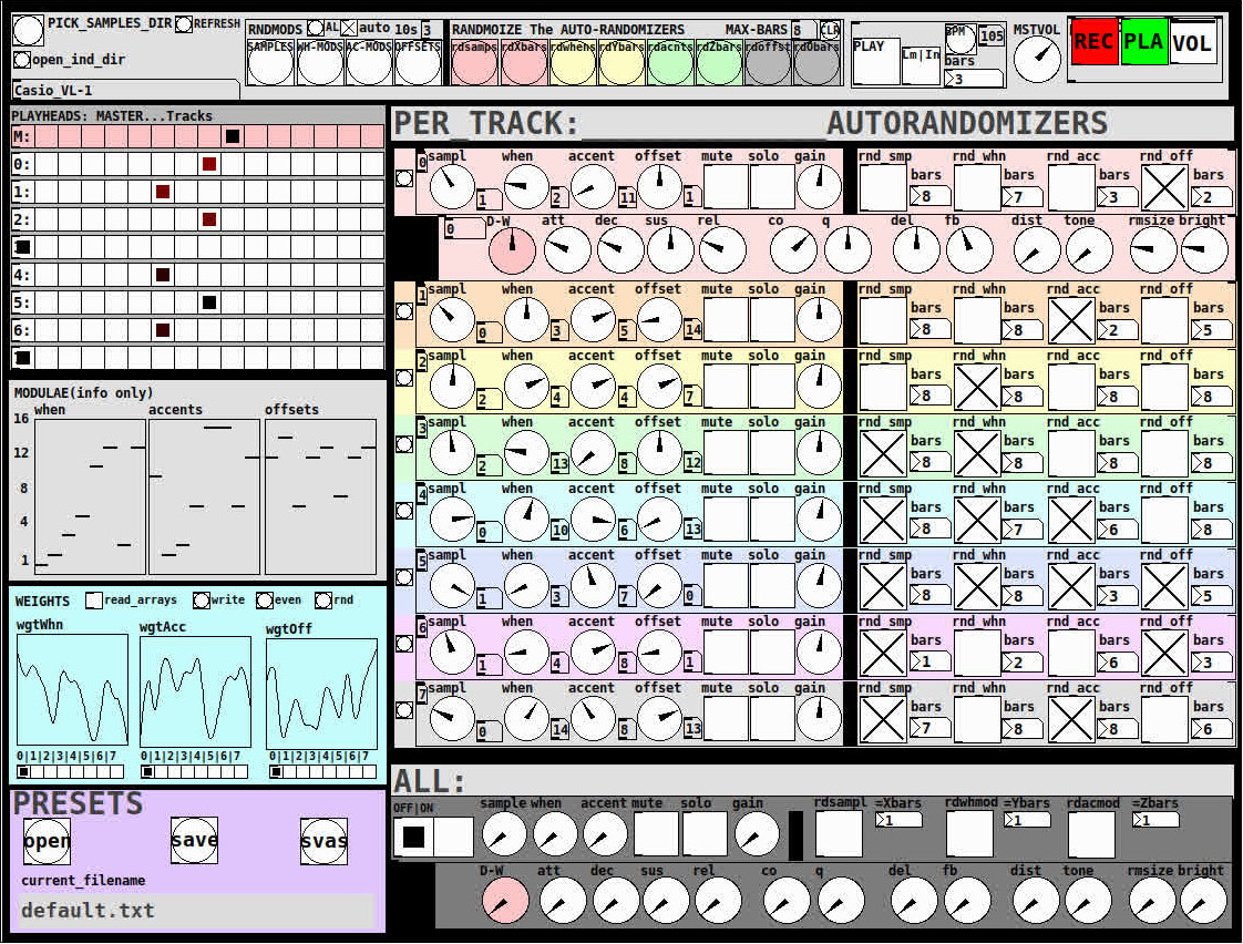
THE 7 SECTIONS:
- GLOBAL:
- to set parameters for all 8 tracks, exs. pick the samples directory from a tof/pmenu or OPEN_IND_DIR (open an independent directory) (see below "Samples"for more detail)
- randomizing parameters, random all. randomize all every 10*seconds, maximum number of bars when randomizing bars, CLR the randomizer check boxes
- PLAY, L(imited) or I(nfinite) counter, if L then number of bars to play before resetting counter, bpm(menu)
- MSTVOL
- transport/recording (on REC files are automatically saved to ./ganymede/recordings with datestamp filename, the output is zexy limited to 98 and the volume controls the boost into the limiter)
- PLAYHEADS:
- indicating where the track is "beating"
- blank=no beat and black-to-red where redder implies greater env~ rms
- MODULAE:
- for information only to show the relative values of the selected modulators
- WEIGHTS:
- sent to [list-wrandom] when randomizing the When, Accent, and Offset modulators
- to use click READ_ARRAYS, adjust as desired, click WRITE, uncheck READ ARRAYS
- EVEN=unweighted, RND for random, and 0-7 for preset shapes
- PRESETS:
- ...self explanatory
-
PER TRACK ACCORDION:
- 8 sections, 1 per track
- each open-closable with the left most bang/track
- opening one track closes the previously opened track
- includes main (always shown)
- with knobs for the sample (with 300ms debounce)
- knobs for the modulators (When, Accent, and Offset) [1..16]
- toggles if you want that parameter to be randomized after X bars
- and when opened, 5 optional effects
- adsr, vcf, delayfb, distortion, and reverb
- D-W=dry-wet
- 2 parameters per effect
-
ALL:
when ON. sets the values for all of the tracks to the same value; reverts to the original values when turned OFF
MIDI:
CC 7=MASTER VOLUME
The other controls exposed to midi are the first four knobs of the accordion/main-gui. In other words, the Sample, When, Accent, and Offset knobs of each track. And the MUTE and SOLO of each track.
Control is based on a midimap file (./midimaps/midimap-default.txt).
So if it is easier to just edit that file to your controller, then just make a backup of it and edit as you need. In other words, midi-learn and changing midimap files is not supported.
The default midimap is:
By track
CCs
| ---TRACK--- | ---SAMPLE--- | ---WHEN--- | ---ACCENT--- | --- OFFSET--- |
|---|---|---|---|---|
| 0 | 16 | 17 | 18 | 19 |
| 1 | 20 | 21 | 22 | 23 |
| 2 | 24 | 25 | 26 | 27 |
| 3 | 28 | 29 | 30 | 31 |
| 4 | 46 | 47 | 48 | 49 |
| 5 | 50 | 51 | 52 | 53 |
| 6 | 54 | 55 | 56 | 57 |
| 7 | 58 | 59 | 60 | 61 |
NOTEs
| ---TRACK--- | ---MUTE--- | ---SOLO--- |
|---|---|---|
| 0 | 1 | 3 |
| 1 | 4 | 6 |
| 2 | 7 | 9 |
| 3 | 10 | 12 |
| 4 | 13 | 15 |
| 5 | 16 | 18 |
| 6 | 19 | 21 |
| 7 | 22 | 24 |
SAMPLES:
Ganymede looks for samples in its ./samples directory by subdirectory.
It generates a tof/pmenu from the directories in ./samples.
Once a directory is selected, it then searches for ./**/.wav (wavs within 1-deep subdirectories) and then ./*.wav (wavs within that main "kit" directory).
I have uploaded my collection of samples (that I gathered from https://archive.org/details/old-school-sample-cds-collection-01, Attribution-Non Commercial-Share Alike 4.0 International Creative Commons License, 90's Old School Sample CDs Collection by CyberYoukai) to the following link on my Google Drive:
https://drive.google.com/file/d/1SQmrLqhACOXXSmaEf0Iz-PiO7kTkYzO0/view?usp=sharing
It is a large 617 Mb .7z file, including two directories: by-instrument with 141 instruments and by-kit with 135 kits. The file names and directory structure have all been laid out according to Ganymede's needs, ex. no spaces, etc.
My suggestion to you is unpack the file into your Path so they are also available for all of your other patches.
MAKING KITS:
I found Kits are best made by adding directories in a "custom-kits" folder to your sampls directory and just adding files, but most especially shortcuts/symlinks to all the files or directories you want to include in the kit into that folder, ex. in a "bongs&congs" folder add shortcuts to those instument folders. Then, create a symnlink to "bongs&congs" in your ganymede/samples directory.
Note: if you want to experiment with kits on-the-fly (while the patch is on) just remember to click the REFRESH bang to get a new tof/pmenu of available kits from your latest ./samples directory.
If you want more freedom than a dynamic menu, you can use the OPEN_IND(depedent)_DIR bang to open any folder. But do bear in mind, Ganymede may not see all the wavs in that folder.
AFTERWARD/NOTES
-
the [hcs/folder_list] [tof/pmenu] can only hold (the first) 64 directories in the ./samples directory
-
the use of 1/16th notes (counter-interval) is completely arbitrary. However, that value (in the [pd global_metro] subpatch...at the noted hradio) is exposed and I will probably incorporate being able to change it in a future version)
-
rem: one of the beauties of this technique is: If you don't like the beat,rhythm, etc., you need only click ALL to get an entirely new beat or any of the other randomizers to re-randomize it OR let if do that by itself on AUTO until you like it, then just take it off AUTO.
-
One fun thing to do, is let it morph, with some set of toggles and bars selected, and just keep an ear out for the Really choice ones and record those or step in to "play" it, i.e. tweak the effects and parameters. It throws...rolls...a lot of them.
-
Another thing to play around with is the notion of Limited (bumpy) or Infinite(flat) sequences in conjunction with the number of bars. Since when and where the modulator triggers is contegent on when it resets.
-
Designed, as I said before, to be played, esp. once it gets rolling, it allows you to focus on the production (instead of writing beats) by controlling the ALL and Individual effects and parameters.
-
Note: if you really like the beat Don't forget to turn off the randomizers. CLEAR for instance works well. However you can't get the back the toggle values after they're cleared. (possible feature in next version)
-
The default.txt preset loads on loadbang. So if you want to save your state, then just click PRESETS>SAVE.
-
[folder_list] throws error messages if it can't find things, ex. when you're not using subdirectories in your kit. No need to worry about it. It just does that.
POSTSCRIPT
If you need any help, more explanation, advise, or have opinions or insight as to how I can make it better, I would love to hear from you.
I think that's >=95% of what I need to tell you.
If I think of anything else, I'll add it below.
Peace thru Music.
Love thru Pure Data.
-s
,
 posted in patch~
Trying to reproduce a sound with Pd
@JMC64 You would need to look up the specs of the VCF on the manufactures website and find its frequency range. They will most likely give the range in hz, so if they say it goes from 8hz to 16khz that would roughly be C1 to C11, so halfway would be C6 or roughly 262hz, remember that frequency is not linear! You can use a chart like http://subsynth.sourceforge.net/midinote2freq.html to convert between note names and hertz or you can have pd do the math for you with the [mtof] and [ftom] objects. Also remember that you do not need to get perfect frequencies, those small knobs have poor resolution and being analog have a fairly wide tolerance, if you went through a dozen of those modules you would find that 0.5 would be slightly different on each of them, so just get close and then tune by ear to perfection.
You can do the same for any module and any parameter, you just need to convert the numbers differently, a VCA will likely have its specs in decibells and a CV input or output in volts.
EDIT: Should mention, you need to look at what the frequency range of the cutoff knob is, not the VCF. Sometimes a VCF or VCO will have a larger range than can be reached by just its frequency knob, the CV inputs can often extend it, so the knob may only go bring you to C8, but a +5 volt signal into the CV input would bring you to C13 because frequency goes up one octave for every volt in a V/oct system like the Doepfers. Generally they will give the tuning range of the knob separately if the VCF can sweep beyond the range of the knob, most modules do not do this though and you should not have to worry about it unless it gives two different values.
 posted in patch~
Having lots of switches into Pd
@alexandros now pwm and digital output work fine, but when I try to merge with digital and analog inputs it goes wrong. the leds flicker randomly. If you remove the code below
// do input pins: flicker stops. :/
int outPins[3] = {2, 4, 7};

int pwmPins[6] = {3, 5, 6, 9, 10, 11};

// a global variable to hold which LED we want to control (either digital or PWM)
int channel = 0;

int inPins[2] = {12, 13};

int analogPins[8] = {0, 1, 2, 3, 4, 5, 6, 7};

void setup() {

   for (int i = 0; i < 3; i++) {
    pinMode(outPins[i], OUTPUT);
  }
    for (int i = 0; i < 6; i++) {
    pinMode(pwmPins[i], OUTPUT);
  }
    for(int i = 0; i < 2; i++) {
    pinMode(inPins[i], INPUT);
  }

  pinMode(A0, INPUT_PULLUP);
  pinMode(A1, INPUT_PULLUP);
  pinMode(A2, INPUT_PULLUP);
  pinMode(A3, INPUT_PULLUP);
  pinMode(A4, INPUT_PULLUP);
  pinMode(A5, INPUT_PULLUP);
  pinMode(A6, INPUT);
  pinMode(A7, INPUT);

//DEFAULT works with thermistors,
//INTERNAL with transitor thermostats
  analogReference(DEFAULT);

  Serial.begin(115200);

}

void loop() {

  //do output pins:

  if (Serial.available()) {
    static int temp;
    byte in = Serial.read();
    if (isDigit(in)) temp = temp * 10 + in - '0';
    else if (in == 'c') {
      channel = temp;
      temp = 0;
    }
    else if (in == 'd') {
      digitalWrite(outPins[channel], temp);
      temp = 0;
    }
    else if (in == 'p') {
      analogWrite(pwmPins[channel], temp);
      temp = 0;
    }
  }

  // do input pins:

Serial.print("analog"); // use "knobs" as a keyword so you can receive
  // the knob values as a list with a [r analog] in Pd
  for(int i = 0; i < 8; i++){
    unsigned int analogVal = analogRead (analogPins[i]);
    Serial.print(" "); // first print a white space to separate the "knob" keyword from the values
    // and the values from each other
    Serial.print(analogVal); // then  print the actual knob value
  }
  Serial.println(); // finally print a newline character to denote end of data for keyword "knobs"

  Serial.print("digital");
  for(int i = 0; i < 2; i++) {
    unsigned int digitalVal = digitalRead(inPins[i]);
    Serial.print(" ");
    Serial.print(digitalVal);
  }
  Serial.println();
}
 posted in I/O hardware diy
Having lots of switches into Pd
@alexandros
This code sort of works with wip_multiple_PWM.pd
// merging works but pwm leds are choppy.

// number of elements in arrays need to
// match for() cycles in void setup and void loop
int pinsIn[2] = {2, 4};
int pinsAnalog[8] = {0, 1, 2, 3, 4, 5, 6, 7};

int pin = 0;
int val = 0;
int pinsOut[2] = {7, 12};

//TMP setup pwm:

// variables to hold pin numbers
int pwmLED1 = 3;
int pwmLED2 = 5;
int pwmLED3 = 6;
int pwmLED4 = 9;
int pwmLED5 = 10;
int pwmLED6 = 11;

// variables to hold pin states
int pwmLEDvalue1;
int pwmLEDvalue2;
int pwmLEDvalue3;
int pwmLEDvalue4;
int pwmLEDvalue5;
int pwmLEDvalue6;

//should this be omitted and use the a
// variable to hold and assemble incoming data
int temporary;

//END TMP pwm setup

void setup()
{
  //set up a total of pins for digital input (has to match number of elements in array)
  for(int i = 0; i < 2; i++)
  pinMode(pinsIn[i], INPUT);

  for (int i = 0; i < 2; i++) {
    pinMode(pinsOut[i], OUTPUT);
    digitalWrite(pinsOut[i], LOW);
  }

//DEFAULT works with thermistors,
//INTERNAL with transitor thermostats

  analogReference(DEFAULT);

  pinMode(A0, INPUT_PULLUP);
  pinMode(A1, INPUT_PULLUP);
  pinMode(A2, INPUT_PULLUP);
  pinMode(A3, INPUT_PULLUP);
  pinMode(A4, INPUT_PULLUP);
  pinMode(A5, INPUT_PULLUP);
  pinMode(A6, INPUT);
  pinMode(A7, INPUT);

//TMP test pwm setup:

  pinMode(pwmLED1, OUTPUT);
  pinMode(pwmLED2, OUTPUT);
  pinMode(pwmLED3, OUTPUT);
  pinMode(pwmLED4, OUTPUT);
  pinMode(pwmLED5, OUTPUT);
  pinMode(pwmLED6, OUTPUT);

  Serial.begin(115200); // perhaps use a faster baud rate
}

void loop()
{
  Serial.print("knobs"); // use "knobs" as a keyword so you can receive
  // the knob values as a list with a [r knobs] in Pd
  for(int i = 0; i < 8; i++){
    unsigned int knob = analogRead (pinsAnalog[i]);
    Serial.print(" "); // first print a white space to separate the "knob" keyword from the values
    // and the values from each other
    Serial.print(knob); // then  print the actual knob value
  }
  Serial.println(); // finally print a newline character to denote end of data for keyword "knobs"

  // the same technique applies to the switches too
  // receive the switch values as a list with [r switches]
  Serial.print("switches");
  for(int i = 0; i < 2; i++) {
    int switchVal = digitalRead(pinsIn[i]);
    Serial.print(" ");
    Serial.print(switchVal);
  }
  Serial.println();

  //handle digital outputs
  if (Serial.available()) {
    static int temp;
    byte in = Serial.read();
    if (isDigit(in)) {
      temp = temp * 10 + in - '0';
    }
    else if (in == 'p') {
      pin = temp;
      temp = 0;
    }
    else if (in == 'v')  {
      val = temp;
      temp = 0;
      digitalWrite(pinsOut[pin], val);
    }
}

//TMP merge test PWMs:
while(Serial.available()){
     byte inByte = Serial.read();
     if((inByte >= '0') && (inByte <= '9'))
       temporary = 10 * temporary + inByte - '0';
     else{
       if(inByte == 'p'){
         pwmLEDvalue1 = temporary;
         temporary = 0;
       }
       else if(inByte == 'q'){
         pwmLEDvalue2 = temporary;
         temporary = 0;
       }
       else if(inByte == 'r'){
         pwmLEDvalue3 = temporary;
         temporary = 0;
       }
       else if(inByte == 's'){
         pwmLEDvalue4 = temporary;
         temporary = 0;
       }
       else if(inByte == 't'){
         pwmLEDvalue5 = temporary;
         temporary = 0;
       }
       else if(inByte == 'u'){
         pwmLEDvalue6 = temporary;
         temporary = 0;
       }
     }
     analogWrite(pwmLED1, pwmLEDvalue1);
     analogWrite(pwmLED2, pwmLEDvalue2);
     analogWrite(pwmLED3, pwmLEDvalue3);
     analogWrite(pwmLED4, pwmLEDvalue4);
     analogWrite(pwmLED5, pwmLEDvalue5);
     analogWrite(pwmLED6, pwmLEDvalue6);
     //digitalWrite(dspLED, dspLEDstate);
   }
}
This is the code without PWM control. It works fine.
//number of elements in arrays need to match for() cycles in void setup
int pinsIn[4] = {6, 7, 8, 9};
int pinsAnalog[8] = {0, 1, 2, 3, 4, 5, 6, 7};

int pin = 0;
int val = 0;
int pinsOut[4] = {2, 3, 4, 5};

void setup()
{
  //set up a total of pins for digital input (has to match number of elements in array)
  for(int i = 0; i < 4; i++)
  pinMode(pinsIn[i], INPUT);

  for (int i = 0; i < 4; i++) {
    pinMode(pinsOut[i], OUTPUT);
    digitalWrite(pinsOut[i], LOW);
  }
//DEFAULT works with thermistors,
//INTERNAL with transitor thermostats
// ELLER var det tvartom???
  analogReference(DEFAULT);

  pinMode(A0, INPUT_PULLUP);
  pinMode(A1, INPUT_PULLUP);
  pinMode(A2, INPUT_PULLUP);
  pinMode(A3, INPUT_PULLUP);
  pinMode(A4, INPUT_PULLUP);
  pinMode(A5, INPUT_PULLUP);
  pinMode(A6, INPUT);
  pinMode(A7, INPUT);

  Serial.begin(115200); // perhaps use a faster baud rate
}

void loop()
{
  Serial.print("knobs"); // use "knobs" as a keyword so you can receive
  // the knob values as a list with a [r knobs] in Pd
  for(int i = 0; i < 8; i++){
    unsigned int knob = analogRead (pinsAnalog[i]);
    Serial.print(" "); // first print a white space to separate the "knob" keyword from the values
    // and the values from each other
    Serial.print(knob); // then  print the actual knob value
  }
  Serial.println(); // finally print a newline character to denote end of data for keyword "knobs"

  // the same technique applies to the switches too
  // receive the switch values as a list with [r switches]
  Serial.print("switches");
  for(int i = 0; i < 4; i++) {
    int switchVal = digitalRead(pinsIn[i]);
    Serial.print(" ");
    Serial.print(switchVal);
  }
  Serial.println();

  //handle digital outputs
  if (Serial.available()) {
    static int temp;
    byte in = Serial.read();
    if (isDigit(in)) {
      temp = temp * 10 + in - '0';
    }
    else if (in == 'p') {
      pin = temp;
      temp = 0;
    }
    else if (in == 'v')  {
      val = temp;
      temp = 0;
      digitalWrite(pinsOut[pin], val);
    }
}
}
and here is the code from tutorial5 from Arduino for Pd'ers. It goes with arduinoforpdrs_tut5.pd
// variables to hold pin numbers
int pwmLED = 9;
int dspLED = 2;
// variables to hold pin states
int pwmLEDvalue;
int dspLEDstate;
//variable to hold and assemble incoming data
int temporary;

void setup()
{
  pinMode(pwmLED, OUTPUT);
  pinMode(dspLED, OUTPUT);
  Serial.begin(9600);
}

void loop()
{
  while(Serial.available()){
    byte inByte = Serial.read();
    if((inByte >= '0') && (inByte <= '9'))
    temporary = 10 * temporary + inByte - '0';
    else{
      if(inByte == 'p'){
        pwmLEDvalue = temporary;
        temporary = 0;
      }
      else if(inByte == 'd'){
        dspLEDstate = temporary;
        temporary = 0;
      }
    }
    analogWrite(pwmLED, pwmLEDvalue);
    digitalWrite(dspLED, dspLEDstate);
  }
}
I am aiming at using same type of array handling as for the digital outs.
Thanks a lot
posted in I/O hardware diy
Having lots of switches into Pd
@alexandros thanks, it all works!
I merged the codes for in and outs and also changed so you can set up all of the pins with arrays (as you did in the latter code). Then you can set up the pins in any order.
Here is the Arduino code. Do you spot any errors I may have introduced?
//number of elements in array need to match for() cycles
int pinsIn[4] = {2, 7, 10, 11};
int pinsAnalog[3] = {0, 2, 3};

int pin = 0;
int val = 0;
// some random pins
int pinsOut[4] = {3, 4, 5, 6};

void setup()
{
  //set up a total of pins for input (has to match number of elements in array)
  for(int i = 0; i < 4; i++)
  pinMode(pinsIn[i], INPUT);

  for (int i = 0; i < 4; i++) {
    pinMode(pinsOut[i], OUTPUT);
    digitalWrite(pinsOut[i], LOW);
  }

  Serial.begin(115200); // perhaps use a faster baud rate
}

void loop()
{
  Serial.print("knobs"); // use "knobs" as a keyword so you can receive
  // the knob values as a list with a [r knobs] in Pd
  for(int i = 0; i < 3; i++){
    unsigned int knob = analogRead (pinsAnalog[i]);
    Serial.print(" "); // first print a white space to separate the "knob" keyword from the values
    // and the values from each other
    Serial.print(knob); // then  print the actual knob value
  }
  Serial.println(); // finally print a newline character to denote end of data for keyword "knobs"

  // the same technique applies to the switches too
  // receive the switch values as a list with [r switches]
  Serial.print("switches");
  for(int i = 0; i < 4; i++) {
    int switchVal = digitalRead(pinsIn[i]);
    Serial.print(" ");
    Serial.print(switchVal);
  }
  Serial.println();

  //handle digital outputs
  if (Serial.available()) {
    static int temp;
    byte in = Serial.read();
    if (isDigit(in)) {
      temp = temp * 10 + in - '0';
    }
    else if (in == 'p') {
      pin = temp;
      temp = 0;
    }
    else if (in == 'v')  {
      val = temp;
      temp = 0;
      digitalWrite(pinsOut[pin], val);
    }
}
}
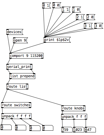
In Pd I was not able to use [r switches] or [r knobs] but had to use [route]. Is this the correct way to use [serial_print]?
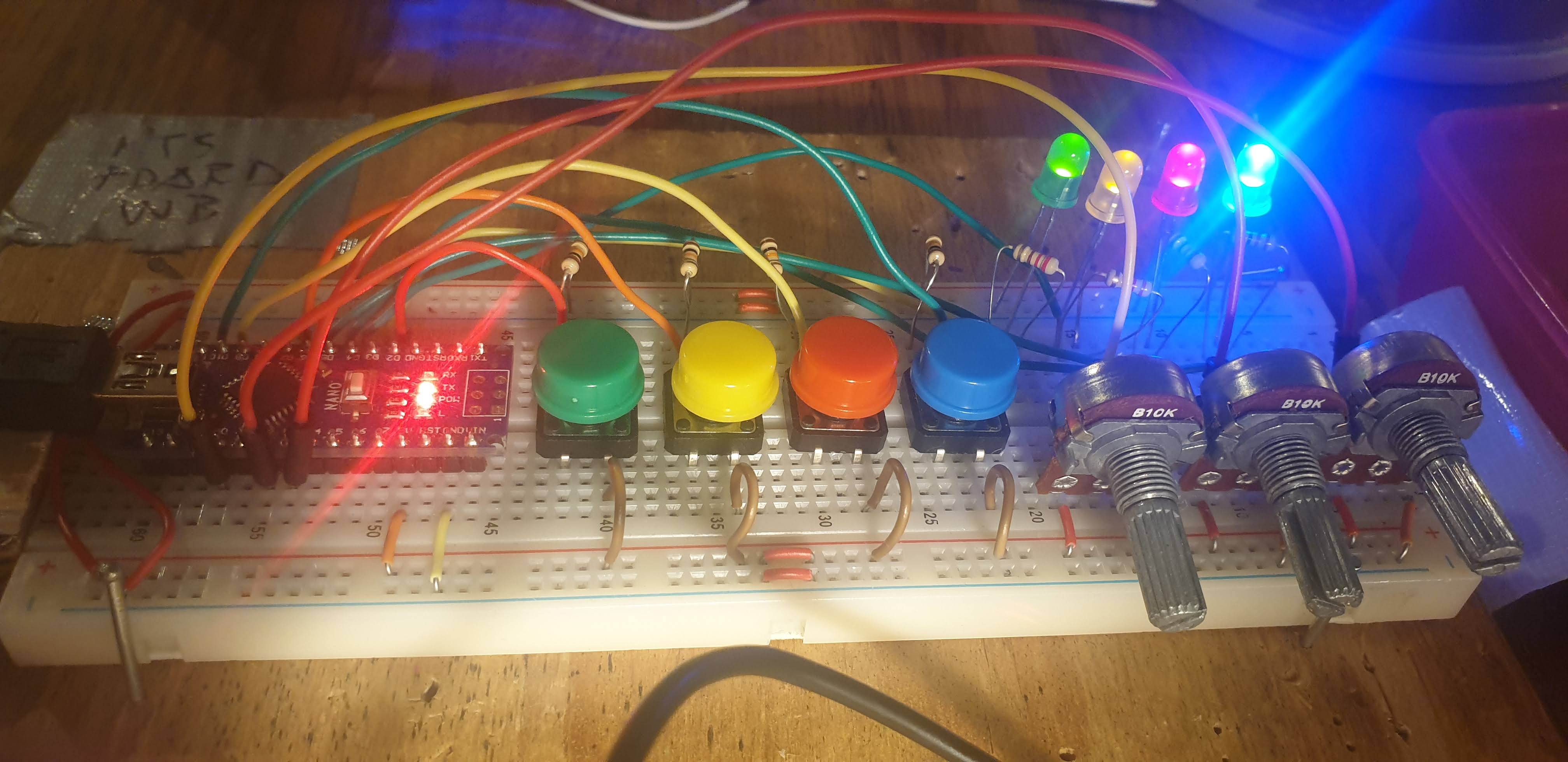
And here it is on the breadboard:
posted in I/O hardware diy
Having lots of switches into Pd
I would suggest to not mix the analog values with the digital ones. The first code could be changed to the following (using Serial.print() with the [serial_print] abstraction):
void setup()
{
  for(int i = 2; i < 14; i++)
  pinMode(i, INPUT);
  Serial.begin(115200); // perhaps use a faster baud rate
}

void loop()
{
  Serial.print("knobs"); // use "knobs" as a keyword so you can receive
  // the knob values as a list with a [r knobs] in Pd
  for(int i = 0; i < 6; i++){
    unsigned int knob = analogRead (i);
    Serial.print(" "); // first print a white space to separate the "knob" keyword from the values
    // and the values from each other
    Serial.print(knob); // then  print the actual knob value
  }
  Serial.println(); // finally print a newline character to denote end of data for keyword "knobs"

  // the same technique applies to the switches too
  // receive the switch values as a list with [r switches]
  Serial.print("switches");
  for(int i = 2; i < 14; i++) {
    int switchVal = digitalRead(i);
    Serial.print(" ");
    Serial.print(switchVal);
  }
  Serial.println();
}
As for writing to several outputs you need to set which output you want to write to and then the value you want to write. Here's an example that writes to several different digital outputs:
int pin = 0;
int val = 0;
// some random pins
int pins[4] = {3, 4, 5, 6];

void setup() {
  for (int i = 0; i < 4; i++) {
    pinMode(pins[i], OUTPUT);
    digitalWrite(pins[i], LOW);
  }

  Serial.begin(115200);
}

void loop() {
  if (Serial.available()) {
    static int temp;
    byte in = Serial.read();
    if (isDigit(in)) {
      temp = temp * 10 + in - '0';
    }
    else if (in == 'p') {
      pin = temp;
      temp = 0;
    }
    else if (in == 'v')  {
      val = temp;
      temp = 0;
      digitalWrite(pins[pin], val);
    }
}
With the code above you can send messages like this one print $1p$2v in Pd to the [comport] object. $1 is the number of the pin you want to light up starting from 0 and incrementing by 1 (so the first pin used which is pin 3 in the Arduino code would be 0 in the Pd patch), and $2 is the value, 0 or 1.
Note though that in the first code (and the code you posted), you're using all digital pins as inputs so there's no pin left to use as output. If you want to combine these two chunks of code you'll have to use less pins as inputs and leave some to be used as outputs.
 posted in I/O hardware diy
JASS, Just Another Synth...Sort-of, codename: Gemini (UPDATED: esp with midi fixes)
JASS, Just Another Synth...Sort-of, codename: Gemini (UPDATED TO V-1.0.1)
jass-v1.0.1( esp with midi fixes).zip
1.0.1-CHANGES:
- Fixed issues with midi routing, re the mode selector (mentioned below)
- Upgraded the midi mode "fetch" abstraction to be less granular
- Fix (for midi) so changing cc["14","15","16"] to "rnd" outputs a random wave (It has always done this for non-midi.)
- Added a midi-mode-tester.pd (connect PD's midi out to PD's midi in to use it)
- Upgrade: cc-56 and cc-58 can now change pbend-cc and mod-cc in all modes
- Update: the (this) readme
INFO: Values setting to 0 on initial cc changes is (given midi) to be expected.
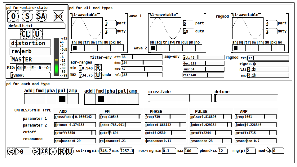
JASS is a clone-based, three wavetable, 16 voice polyphonic, Dual-channel synth.
With...
- The initial, two wavetables combined in 1 of 5 possible ways per channel and then adding those two channels. Example: additive+frequency modulation, phase+pulse-modulation, pulse-modulation+amplitude modulation, fm+fm, etc
- The third wavetable is a ring modulator, embedded inside each mod type
- 8 wave types, including a random with a settable number of partials and a square with a settable dutycycle
- A vcf~ filter embedded inside each modulation type
- The attack-decay-release, cutoff, and resonance ranges settable so they immediately and globally recalculate all relevant values
- Four parameters /mod type: p1,p2, cutoff, and resonance
- State-saving, at both the global level (wavetables, env, etc.), as well as, multiple "substates" of for-each-mod-type settings.
- Distortion, reverb
- Midiin, paying special attention to the use of 8-knob, usb, midi controllers (see below for details)
- zexy-limiters, for each channel, after the distortion, and just before dac~
Instructions
Requires: zexy
for-entire-state
- O: Open preset. "default.txt" is loaded by...default
- S: Save preset (all values incl. the multiple substates) (Note: I have Not included any presets, besides the default with 5 substates.)
- SA: Save as
- TEST: A sample player
- symbol: The filename of the currently loaded preset
- CL: Clear, sets all but a few values to 0
- U: Undo CL
- distortion,reverb,MASTER: operate on the total out, just before the limiter.
- MIDI (Each selection corresponds to a pgmin, 123,124,125,126,127, respectively, see below for more information)
- X: Default midi config, cc[1,7,8-64] available
- M: Modulators;cc[10-17] routed to ch1&ch2: p1,p2,cutoff,q controls
- E: Envelopes; cc[10-17] routed to filter- and amp-env controls
- R: Ranges; cc[10-17] routed to adr-min/max,cut-off min/max, resonance min/max, distortion, and reverb
- O: Other; cc[10-17] routed to rngmod controls, 3 wavetypes, and crossfade
- symbol: you may enter 8 cc#'s here to replace the default [10-17] from above to suit your midi-controller's knob configuration; these settings are saved to file upon entry
- vu: for total out to dac~
for-all-mod-types
- /wavetable
- graph: of the chosen wavetype
- part: partials, # of partials to use for the "rn" wavetype; the resulting, random sinesum is saved with the preset
- duty: dutycycle for the "du" wavetype
- type: sin | square | triangle | saw | random | duty | pink (pink-noise: a random sinesum with 128 partials, it is not saved with the preset) | noise (a random sinesum with 2051 partials, also not saved)
- filter-env: (self-explanatory)
- amp-env: (self-explanatory)
- rngmod: self-explanatory, except "sign" is to the modulated signal just before going into the vcf~
- adr-range: min,max[0-10000]; changing these values immediately recalculates all values for the filter- and amp-env's scaled to the new range
- R: randomizes all for-all-mod-types values, but excludes wavetype "noise"; rem: you must S or SA the preset to save the results
- U: Undoes R
for-each-mod-type
- mod-type-1: (In all cases, wavetable1 is the carrier and wavetable2 is the modulator); additive | frequency | phase | pulse | amplitude modulation
- mod-type-2: Same as above; mod-type-2 May be the same type as mod-type-1
- crossfade: Between ch1 and ch2
- detune: Applied to the midi pitch going into ch2
- for-each-clone-type controls:
- p1,p2: (self-explanatory)
- cutoff, resonance: (self-explanatory)
- navigation: Cycles through the saved substates of for-each-mod-type settings (note: they are lines on the end of a [text])
- CP: Copy the current settings, ie. add a line to the end of the [text] identical to the current substate
- -: Delete the current substate
- R: Randomize all (but only a few) substate settings
- U: Undo R
- cut-rng: min,max[0-20000] As adr-range above, this immediately recalculates all cutoff values
- res-rng: min,max[0-100], same as previously but for q
- pbend: cc,rng: the pitchwheel may be assigned to a control by setting this to a value >7 (see midi table below for possibilities); rng is in midi pitches (+/- the value you enter)
- mod-cc: the mod-wheel may be assigned to a control [7..64] by setting this value
midi-implementation
| name | --- | Description |
|---|---|---|
| sysex | not supported | |
| pgmin | 123,124,125,126,127; They set midi mode | |
| notein | 0-127 | |
| bendin | pbend-cc=7>pitchbend; otherwise to the cc# from below | |
| touch | not supported | |
| polytouch | not supported |
cc - basic (for all midi-configs)
| # | name | --- | desciption |
|---|---|---|---|
| 1 | mod-wheel | (assignable) | |
| 7 | volume | Master |
cc - "X" mode/pgmin=123
| cc | --- | parameter |
|---|---|---|
| 8 | wavetype1 | |
| 9 | partials 1 | |
| 10 | duty 1 | |
| 11 | wavetype2 | |
| 12 | partials 2 | |
| 13 | duty 2 | |
| 14 | wavetype3 | |
| 15 | partials 3 | |
| 16 | duty 3 | |
| 17 | filter-att | |
| 18 | filter-dec | |
| 19 | filter-sus | |
| 20 | filter-rel | |
| 21 | amp-att | |
| 22 | amp-dec | |
| 23 | amp-sus | |
| 24 | amp-rel | |
| 25 | rngmod-freq | |
| 26 | rngmod-sig | |
| 27 | rngmod-filt | |
| 28 | rngmod-amp | |
| 29 | distortion | |
| 30 | reverb | |
| 31 | master | |
| 32 | mod-type 1 | |
| 33 | mod-type 2 | |
| 34 | crossfade | |
| 35 | detune | |
| 36 | p1-1 | |
| 37 | p2-1 | |
| 38 | cutoff-1 | |
| 39 | q-1 | |
| 40 | p1-2 | |
| 41 | p2-2 | |
| 42 | cutoff-2 | |
| 43 | q-2 | |
| 44 | p1-3 | |
| 45 | p2-3 | |
| 46 | cutoff-3 | |
| 47 | q-3 | |
| 48 | p1-4 | |
| 49 | p2-4 | |
| 50 | cutoff-4 | |
| 51 | q-4 | |
| 52 | p1-5 | |
| 53 | p2-5 | |
| 54 | cutoff-5 | |
| 55 | q-5 | |
| 56 | pbend-cc | |
| 57 | pbend-rng | |
| 58 | mod-cc | |
| 59 | adr-rng-min | |
| 60 | adr-rng-max | |
| 61 | cut-rng-min | |
| 62 | cut-rng-max | |
| 63 | res-rng-min | |
| 64 | res-rng-max |
cc - Modes M, E, R, O
Jass is designed so that single knobs may be used for multiple purposes without reentering the previous value when you turn the knob, esp. as it pertains to, 8-knob controllers.
Thus, for instance, when in Mode M(pgm=124) your cc send the signals as listed below. When you switch modes, that knob will then change the values for That mode.
In order to do this, you must turn the knob until it hits the previously stored value for that mode-knob.
After hitting that previous value, it will begin to change the current value.
cc - Modes M, E, R, O assignments
Where [10..17] may be the midi cc #'s you enter in the MIDI symbol field (as mentioned above) aligned to your particular midi controller.
| cc# | --- | M/pgm=124 | --- | E/pgm=125 | --- | R/pgm=126 | --- | O/pgm=127 |
|---|---|---|---|---|---|---|---|---|
| 10 | ch1:p1 | filter-env:att | adr-rng-min | rngmod:freq | ||||
| 11 | ch1:p2 | filter-env:dec | adr-rng-max | rngmod:sig | ||||
| 12 | ch1:cutoff | filter-env:sus | cut-rng-min | rngmod:filter | ||||
| 13 | ch1:q | filter-env:re | cut-rng-max | rngmod:amp | ||||
| 14 | ch2:p1 | amp-env:att | res-rng-min | wavetype1 | ||||
| 15 | ch2:p2 | amp-env:dec | res-rng-max | wavetype2 | ||||
| 16 | ch2:cutoff | amp-env:sus | distortion | wavetype3 | ||||
| 17 | ch2:q | amp-env:rel | reverb | crossfade |
In closing
If you have anywhere close to as much fun (using, experimenting with, trying out, etc.) this patch, as I had making it, I will consider it a success.
For while an arduous learning curve (the first synth I ever built), it has been an Enormous pleasure to listen to as I worked on it. Getting better and better sounding at each pass.
Rather, than say to much, I will say this:
Enjoy. May it bring a smile to your face.
Peace through love of creating and sharing.
Sincerely,
Scott
posted in patch~
abs-fetch-slider: using a value (slider) multiple ways based on creation argument
abs-fetch-slider: using a value (slider) multiple ways based on creation argument
abs-fetch-slider-help.pd
abs-fetch-slider.pd
;
reuse a value by only changing the value;
once the value matches the previously set value;
for that index/creation argumet.;
;
USECASE:;
Getting a (hardware) knob to serve multiple functions;
by only having it change its value once the previous value for that index is hit.;
(See the help file for details, using two ctlin to set multiple values)
;
Background:;
I have found it very frustrating that when using hardware you can't use one knob for multiple purposes because the knob is literally always in the last state you left it.;
;
one creation argument: the identifying index;
two inlets: left: the incoming value and right the index;
one outlet the value for that index
So...
When you change the index, just change the knob until the audio, image, value, etc., i.e. result starts changing.
It will ONLY change once the previously set value for that index is hit..
So it "saves state".
Peace.
Stay Safe.
-S
posted in abstract~
can't find [knob]
@raynovich Uliss CEAMMC has a 64-bit gui knob [ui.knob]
It is available for 64 bit Pd in windows and probably for other os's through Deken.
If you need to compile it then I think this is the correct link.....
https://github.com/uliss/pure-data/tree/ceammc/ceammc/distrib
For Linux there is an OS specific distribution for many systems through Snap.....
https://snapcraft.io/pd-ceammc
David.
P.S. All of Millers Pd downloads.... 0.49 0.50 0.51........ and before..... and after...... are "Vanilla" as they have no extra externals bundled into the download.
.......... Externals can be added through "Deken" like this........
You can install externals easily for your system by opening help from the top menu in Pd.
Then click "Find Externals" and in the search box type (for example)........ knob
All libraries that are available for your version of Pd that have an object with knob in its name will appear.
Select the library you want and follow the instructions and restart Pd when it is done.
 posted in technical issues
can't find [knob]
couldn't think how else to word it
I'm told that [knob] is in iemlib so i've installed it through synaptic package manager and everything in there (apart from [knob]) seems to be working fine. The problem is... that knob.pd isn't actually in the folder. Neither is it's help files or anything. I was then told that [mknob] in moonlib is a good alternative... so i installed that and this time the mknob-help.pd file is there and there is an mknob.pd_linux but there is no mknob.pd so not working either
All other externals in both libraries are working fine so it seems like they are installed correctly. but then im using synaptic so why wouldn't they be. The preoblem seems to be that the actual files are missing from the downloaded folders.
any ideas on how to fix? Perhaps if i could just get a copy of mknob.pd or knob.pd and stick it in my extras folder
 posted in technical issues