Where does latency come from in Pure Data?
@Pandas As above..... Pd has an input > output delay equal to its block size.
Put something in and it will output 64 samples later.
But the soundcard cannot convert that to analogue instantly... so we add a buffer that gives it time to process the audio before the next block arrives.... MOTU 2-3ms with ASIO... On board soundcard usually 30-80ms.
I see you posted elsewhere on the forum..... https://forum.pdpatchrepo.info/topic/14495/sync-to-external-daw-midi-clock-audio-latency
I don't know those programs and maybe someone else will help.
Sending the audio samples to another program through a port will still not be instantaneous... but should be close unless you are listening to it at the same time.... but even media players will buffer at least 512 samples before they play a stream.
Does QSynth have compensation settings to delay the midi and attempt to match the audio timing?
What is your OS?
As you are communicating with software rather than a DAC you could try reducing the Delay (mSecs) in Pd media settings,,,,,, down to 3, then 2, then 1.. 0 probably not but you never know.... basically until it hangs and then go back to the last setting that worked.
Apply but don't save the settings until you are done.... or Pd might not start or might not let you change them again while it is "stuck" even if you restart it.
There is a fix for that..... I will upload it if that happens..
Running Pd at 96kHz audio rate should I think reduce the 64 sample (Pd internal) block delay.... you could try that too...... I think it should output in half the 48kHz time.
And try this..... it might help....... depends what you are wanting to achieve...... https://forum.pdpatchrepo.info/topic/13125/batch-processing-audio-faster-than-realtime
David.
 posted in technical issues
Where does latency come from in Pure Data?
The amount of input-->output latency comes from the soundcard driver settings, specifically, the hardware buffer size.
"Where does latency come from" is this:
The audio card driver processes blocks of audio. (If it didn't process blocks of audio, then it would have to call into audio apps once per sample. There is no general purpose computer that can handle 40000+ interrupts per second with reliable timing. The only choice is to clump the samples into blocks so that you can do e.g. a few dozen or hundred interrupts per second.)
Audio apps can't start processing a block of input until the entire block is received. Obviously this is at the end of the block's time window. You can't provide audio samples at the beginning of a block for audio which hasn't happened yet.
You can't hear a block of output until it's processed and sent to the driver.
| --- block 1 --- | --- block 2 --- |
| input.......... |                 |
|                \|                 |
|                 \_output......... |
This is true for all audio apps: it isn't a Pd problem. Also Pd's block size cannot reduce latency below the soundcard's latency.
You can't completely get rid of latency, but with system tuning, you can get the hardware buffer down to 5 or 6 ms (sometimes even 2 or 3), which is a/ good enough and b/ as good as it's going to get, on current computers.
hjh
 posted in technical issues
Round trip latency tests
yes, Katja's meter measures 1 sample latency additionally, so real latency is -1 sample.
here are threads of other forums:
https://forum.rme-audio.de/viewtopic.php?id=23459
linking to
https://web.archive.org/web/20160315074034/https://www.presonus.com/community/Learn/The-Truth-About-Digital-Audio-Latency
and an older comparision:
parts 1 2 3:
https://original.dawbench.com/audio-int-lowlatency.htm
 posted in technical issues
Circular buffer issues
@jameslo said:
Honestly, I didn't know if that was @fintg's requirement,
It's certainly a reasonable guess. If the requirement instead were "I just played something cool; write the last 10 seconds to disk" you can do that without a circular buffer at all.
I was just surprised and annoyed that one can only access the delay line's internal buffer at audio rate (and was hoping that someone would prove me wrong).
Access to the internal buffer wouldn't be very useful without also knowing the record-head position. In that case delwrite~ would need an outlet for the current frame being written.
That would actually be a very nice feature request.
In SuperCollider as well, DelayN, DelayL and DelayC don't give you access to the internal buffer. But you can create your own buffer and write into it, with total control over phase, with BufWr -- and, because you control the write phase, you already know what it is. It's quite nice way to do it.
Basically the lack of ipoke~ in vanilla causes some headaches.
Look at the hoops I have to jump through! The extra memory I have to use!
I don't think there is any way to do this without using some extra memory.
In a circular buffer, you have:
|~~~~~~ new audio ~~~~~~|~~~~~~ old audio ~~~~~~|
                        ^ record head
When you write to disk, naturally you want the old audio earlier in the file. There are only two ways to do that. One is to write the "old" chunk without closing the file, and append the "new" chunk, and then close the file.
In SC, if I know the record head position, I'd do it like:
buf.write(path, "wav", "int24", startFrame: recHead, leaveOpen: true, completionMessage: { |buf|
    buf.writeMsg(path, "wav", "int24", numFrames: recHead, startFrame: 0, leaveOpen: false)
});
AFAICS Pd does not support this, so you're left with duplicating new after old data. (FWIW, though, there's plenty of memory in modern computers; I wouldn't lose sleep over this.)
Then there is the problem of synchronous vs asynchronous disk access. AFAICS Pd's disk access is synchronous, and because the control layer is triggered from the audio loop, slow disk access could cause audio dropouts. OS file system caching might reduce the risk of that, but you never know. Ross Bencina's article about real-time audio performance advises against time-unbounded operations in the audio thread.
SC's buffer read/write commands run in a lower priority thread; wrt audio, they are asynchronous. This is good for audio stability, but it means that, by the time you get around to writing, the record head has moved forward. So, even though I could do the two-part write easily, I'd get a few ms of new data at the start of the file. I think I would solve that by allocating an extra, say, 2 seconds and then just don't write the 2 seconds after the sampled-held recHead value: startFrame: recHead + (s.sampleRate * 2). (If it takes 2 seconds to write a 10 second audio file, then you have bigger problems than circular buffers.) Then the record head can move freely into that zone without affecting audio written to disk.
hjh
posted in technical issues
Failed to autostart PD on Pi using service
This is a continuation to the issue I wanted to solved in this topic. It just went to different places so I though I will open a new topic to this problem I'm facing.
I have a pd patch that doing some audio playback reading some files from buffer. I'm running it on my Pi4.
I wanted it to start on boot every time and to be able to reset itself if crashing for some reason.
I was suggested to use that service script:
[Unit]
Description=My PureData service

[Service]
Type=simple
LimitNOFILE=1000000
ExecStart=/usr/bin/puredata -nogui  -open /home/pi/mypatch.pd
WorkingDirectory=/home/pi
User=pi
Group=pi
Restart=always
# Restart service after 10 seconds if service crashes
RestartSec=10

[Install]
WantedBy=multi-user.target
The above was working great using the built in 3.5mm audio jack.
I then bought UGREEN USB audio interface as I was facing with some poor audio quality at the output.
I set the audio preference in PD to choose the USB Audio Interface as the output.
When I boot the Pi I'm getting this error from the service (see picture)
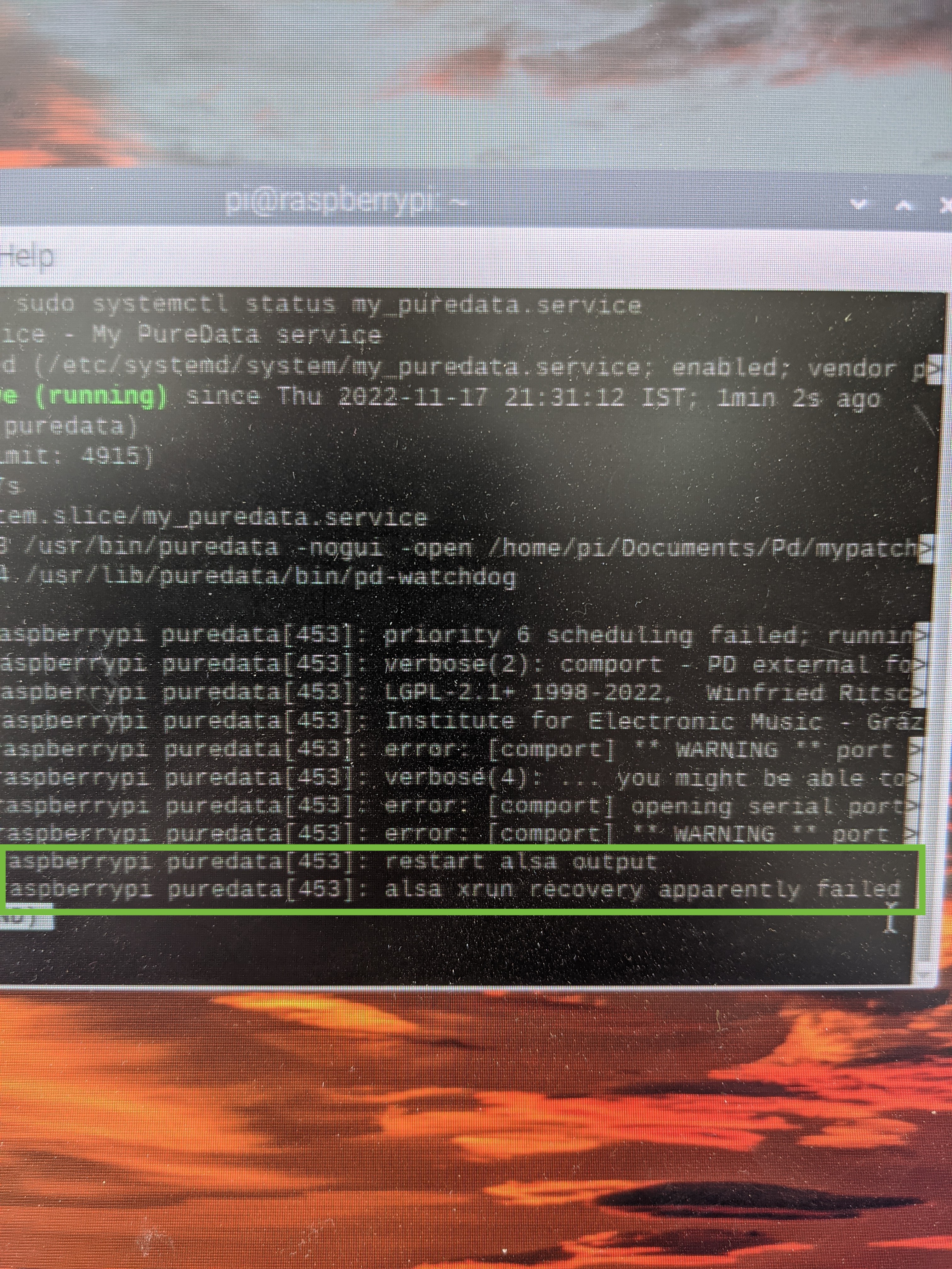
If I'm typing sudo systemctl restart my_puredata.service the PD patch is back to work just fine. No Alsa error, but on the initial boot it is not working.
Any idea why this happen when using the USB AudioInterface? anything I can do in order to make it work?
So If to conclude:
When I start the same pd patch using the same service script but without a USB audio interface is working just fine.
When I start the same pd patch with the USB audio interface but using the autostart file:
sudo nano /etc/xdg/lxsession/LXDE-pi/autostart
Is also working just fine.
But the combination of the USB audio interface and the service script is just not working.
Thanks for any help.
 posted in technical issues
phase index of an oscillator and 1 sample delay in pd?
@KMETE
the Max patch looks like feedback-FM to me. For PM the + would be placed between phasor and circle, if I'm not mistaken.
And with 1000 ms delay, as I read the Max patch? there would be no need for 1 sample-blocks.
A thread on this topic:
https://forum.pdpatchrepo.info/topic/6185/feedback-fm-algorithm
DC-blocking you can do with [hip~ 20] for example (I'd put it in the feedback-loop).
cycle object
[cos~] ? Is a cosine-tabel, to get a sine you can drive it like this:
[phasor~]
|
[-~ 0.25]
|
[cos~]
Offtopic: Pd's cosine has a slight DC-offset.
https://forum.pdpatchrepo.info/topic/13709/bug-osc-cos-circle-asymmetry-drifting-out-of-phase
@alexandros said:
Creating a one-sample delay is achieved by placing your objects in a subpatch and putting a
[block~ 1]object in there. Then you have to use[tabsend~]and[tabreceive~]instead of[delwrite~]and[delread~]to achieve the one-sample delay.
Yes. And be aware of the importance of creating [tabsend~] beforehand of [tabreceive~] . You can read about in the Pd documentation 3.audio.example > G05.execution.order.pd
For feedback, I usually build subpatches with such a dummy-connection, save the patch, and delete the dummy cable lastly and save again, for perceving the execution order and avoiding a dsp-loop.
[delwrite~] and [delread~] can become as short as 1 sample, too.
In both [osc~] and [phasor~], the phase is set by control messages, but since you'll have a one-sample block size, that shouldn't be a problem, you can just set the phase to what ever you like and it will be reset at the next sample block (one sample later).
This is one of the biggest myths in Pd (at least for me), but unfortunately not true. (Vanilla 52.2)
See vphasor~-help : https://github.com/dotmmb/mmb
Still the same, if you put it in a subpatch with [block~ 1].
Documentation is lacking here. There are very few timing- sample- or phase-critical control-objects that are able to update (sub-)sample-accurately in-between block-boundaries of 64 samples minimum:
I only know of [bang~], [metro], [delay], [pipe], [vline~]
posted in technical issues
Convert analog reading of a microphone back into sound
@MarcoDonnarumma Just had a cursory look at you video.... very good.
So you will understand more musical tech terms.
With your low sample rate the steps in the waveform are massive. The result is approximately what you would ask of a "fuzz" box.
Your ears only hear the rapid changes where the waveform rises or falls vertically. Your brain can only interpret the audio that way as it gets no intermediate information.
A rapid rise or fall like those you see in the scope are..... because the signal rate is now (after [sig~] ) 44100 samples per second..... actually a very high frequency signal....... one half (the left or right half) of a 22KHz "note".
Usually called "aliasing"...... they are there because there was no information before or after to give the real analogue slope of the wave before it was sampled.
For CD audio the rate is also 44100Hz. The Nyquist is 22050Hz and a low pass filter in the DAC removes everything above 20000Hz so as to remove such artefacts.
Putting a [lop] will smooth out those steps and approximate the original waveform as it was originally sampled. The downside is that you will no longer hear the audio because it is likely outside the range of most peoples hearing (in this case only!.... with audio below 40Hz..... if it was a 200Hz note you would hear it).
If you put a [lop~] (between [sig~] and [dac~] with a fader connected to its right inlet with a range of say 0.3 to 40 you can play with the fader to get an audible signal that is close to what you want to hear.
A sort of "depth of fuzz".
You might need a slightly different range on the fader..... 0.1 to 25 or something.
Looking at your video....... seeing (yes, ok, hearing) that you need audible sound.... not 192KHz audiophile sound.... and bearing in mind the original 40Hz analogue signal is inaudible to a lot of people, I don't think the clock problem is going to have a significant effect.
But if you are mistaken about the 40Hz maximum and there is actually more information that you need....... think heartbeat (low) + blood rushing (high) then upping your sample rate from the arduino will be necessary to get the higher frequencies.
500Hz sample rate will only give you up to 250Hz of audio information, just like 44100Hz only renders 22050Hz for our delectation.
David.
P.S. I don't much like maths..... not true..... it is fascinating but too hard for my feeble brain.
But without bothering to work it out, in theory, to preserve the signal the [lop] should be just below half the nyquist... so for 500Hz sampling a [lop~ 240]  ?? should do that.
So I was way off base with the [lop~] values I posted above.
The signal would be very reduced (much lower I think) with the values I gave above.
However, [lop~] is not a very "sharp" filter... low dB/octave...... so maybe I was not in fact wrong...... and anyway you will need some distortion so as to properly hear your 40Hz note.
I hope you like to have someone struggling alongside you while you work.
I have to research what that means when the signal has already been oversampled by [sig~]..... but I think it doesn't matter.
Someone clever will tell us first no doubt.
@jameslo 's solution above should give a better outcome though than with a rather uncertain value for [lop~].
It will depend on what you need from your patch.
posted in technical issues
Convert analog reading of a microphone back into sound
Thanks @whale-av David, several good pointers in your reply.
The sampling period is continuously updated. It's a basic method using fifo and timer. Do you perhaps have suggestions for a more precise measurement technique?
Yes, you are right, the clocking issue may be where to look into first. Incoming values are not regulated yet, I'll get down to do that now (was hoping to get a more or less stable sampling period from the arduino, probably naive.) And thanks for the link!
and now that I read you about tabwrite~ I see that I always understood it wrong  Thanks.
to your P.S.: Yess, that sounds like one of the things I was missing. It could be. If this is the case, the patch is fine and the problem is the low sampling rate, then I can see two options:
- increase the sampling rate in the arduino. I found this tutorial that gets you, allegedly, at 38.5kHz sampling rate on analogIn
or - would it make sense to prepare the signal in a subpatch with a low sampling rate matching the arduino's and then in a parent do upsampling and interpolation before sending out to processing?
Ok, gonna work on it and come back with updates.
Marco
 posted in technical issues
Raspberry Pi Bluetooth Speaker not showing up in Audio preferences
@eulphean said:
I'm using pure data on a raspberry pi 3+ for a project. I have bluetooth configured properly on it. I can send regular audio to bluetooth speaker connected, but the preferences -> audio in PureData doesn't show the bluetooth speaker. It only shows internal audio card or if I have a USB audio card, that shows too. But no bluetooth device.
How do I configure that? Do I need to use jack or something to route audio to bluetooth for Pd?
My experience with Bluetooth audio in Linux has been:
-
JACK has zero tolerance for the audio driver ever being late -- expect crashes or system lockups if you try to route audio from JACK to Bluetooth. That is, just don't.
-
PulseAudio's support for BT audio is pretty good -- the "regular audio" that you spoke of. Audio production apps typically bypass PulseAudio, in which case BT audio may simply not be supported for them. That is, I expect you'd hit the same problem with SuperCollider, Audacity, Ardour, VCV Rack etc etc etc.
I'm not aware of a solution... That's not to say that there absolutely isn't one, but the Linux audio space is not unified as it is in Mac so audio device support may not be universal.
hjh
posted in technical issues
Audio click occur when change start point and end point using |phasor~| and |tabread4~|
@Junzhe-hou said:
@ddw_music Hi professor!?!? good to see you here!

Yes, it's me -- I almost didn't notice your username 
I read your email last week but im so confused with your
patch--varispeed-segment:|noise~|
|
|lop~ 3|
|
|*~ 30|
|
|+~ 1|
This is just a way to generate a modulator for the playback rate. It could be any other modulator (LFO, envelope, anything).
After that, this is multiplied by a sample rate scaling factor.
As you asked jameslo: "if sample rate (in audio setting) changed the result sound different":
-
If the file sample rate is 96 kHz and the soundcard sample rate is 96 kHz, then normal-speed playback is to move forward exactly 1 sample in the file for every output sample.
-
If the file sample rate is 96 kHz and the soundcard sample rate is 48 KHz, then normal-speed playback is to move forward exactly 2 samples in the file for every output sample. (If you playback at 1:1, then the file will sound slower at the lower soundcard sample rate.)
This was one of the big reasons for me to make [soundfiler2] in my abstraction set. It calculates file_sr / system_sr and saves this in a value object named after the ID+"scale". If you multiply the playback rate by this scaling factor, then the file should sound correct at any system sample rate.
(BTW you would have the same issue in SuperCollider: PlayBuf.ar(1, bufnum, rate: 1) will sound different depending on the hardware sample rate, but PlayBuf.ar(1, bufnum, rate: BufRateScale.kr(bufnum)) would sound the same, except maybe for aliasing when downsampling.)
You method "L inlet = rate * scale for sample increment",so is the rate always changing?
Yes -- variable-speed playback.
@jameslo "I'm sorry if I just did your student's homework" -- actually this isn't for my class -- independent project. There are still some students who do hard things just because it's fun to overcome challenges 
hjh
posted in technical issues