Having lots of switches into Pd
@alexandros now pwm and digital output work fine, but when I try to merge with digital and analog inputs it goes wrong. the leds flicker randomly. If you remove the code below
// do input pins: flicker stops. :/
int outPins[3] = {2, 4, 7};

int pwmPins[6] = {3, 5, 6, 9, 10, 11};

// a global variable to hold which LED we want to control (either digital or PWM)
int channel = 0;

int inPins[2] = {12, 13};

int analogPins[8] = {0, 1, 2, 3, 4, 5, 6, 7};

void setup() {

   for (int i = 0; i < 3; i++) {
    pinMode(outPins[i], OUTPUT);
  }
    for (int i = 0; i < 6; i++) {
    pinMode(pwmPins[i], OUTPUT);
  }
    for(int i = 0; i < 2; i++) {
    pinMode(inPins[i], INPUT);
  }

  pinMode(A0, INPUT_PULLUP);
  pinMode(A1, INPUT_PULLUP);
  pinMode(A2, INPUT_PULLUP);
  pinMode(A3, INPUT_PULLUP);
  pinMode(A4, INPUT_PULLUP);
  pinMode(A5, INPUT_PULLUP);
  pinMode(A6, INPUT);
  pinMode(A7, INPUT);

//DEFAULT works with thermistors,
//INTERNAL with transitor thermostats
  analogReference(DEFAULT);

  Serial.begin(115200);

}

void loop() {

  //do output pins:

  if (Serial.available()) {
    static int temp;
    byte in = Serial.read();
    if (isDigit(in)) temp = temp * 10 + in - '0';
    else if (in == 'c') {
      channel = temp;
      temp = 0;
    }
    else if (in == 'd') {
      digitalWrite(outPins[channel], temp);
      temp = 0;
    }
    else if (in == 'p') {
      analogWrite(pwmPins[channel], temp);
      temp = 0;
    }
  }

  // do input pins:

Serial.print("analog"); // use "knobs" as a keyword so you can receive
  // the knob values as a list with a [r analog] in Pd
  for(int i = 0; i < 8; i++){
    unsigned int analogVal = analogRead (analogPins[i]);
    Serial.print(" "); // first print a white space to separate the "knob" keyword from the values
    // and the values from each other
    Serial.print(analogVal); // then  print the actual knob value
  }
  Serial.println(); // finally print a newline character to denote end of data for keyword "knobs"

  Serial.print("digital");
  for(int i = 0; i < 2; i++) {
    unsigned int digitalVal = digitalRead(inPins[i]);
    Serial.print(" ");
    Serial.print(digitalVal);
  }
  Serial.println();
}
 posted in I/O hardware diy
Having lots of switches into Pd
@alexandros
This code sort of works with wip_multiple_PWM.pd
// merging works but pwm leds are choppy.

// number of elements in arrays need to
// match for() cycles in void setup and void loop
int pinsIn[2] = {2, 4};
int pinsAnalog[8] = {0, 1, 2, 3, 4, 5, 6, 7};

int pin = 0;
int val = 0;
int pinsOut[2] = {7, 12};

//TMP setup pwm:

// variables to hold pin numbers
int pwmLED1 = 3;
int pwmLED2 = 5;
int pwmLED3 = 6;
int pwmLED4 = 9;
int pwmLED5 = 10;
int pwmLED6 = 11;

// variables to hold pin states
int pwmLEDvalue1;
int pwmLEDvalue2;
int pwmLEDvalue3;
int pwmLEDvalue4;
int pwmLEDvalue5;
int pwmLEDvalue6;

//should this be omitted and use the a
// variable to hold and assemble incoming data
int temporary;

//END TMP pwm setup

void setup()
{
  //set up a total of pins for digital input (has to match number of elements in array)
  for(int i = 0; i < 2; i++)
  pinMode(pinsIn[i], INPUT);

  for (int i = 0; i < 2; i++) {
    pinMode(pinsOut[i], OUTPUT);
    digitalWrite(pinsOut[i], LOW);
  }

//DEFAULT works with thermistors,
//INTERNAL with transitor thermostats

  analogReference(DEFAULT);

  pinMode(A0, INPUT_PULLUP);
  pinMode(A1, INPUT_PULLUP);
  pinMode(A2, INPUT_PULLUP);
  pinMode(A3, INPUT_PULLUP);
  pinMode(A4, INPUT_PULLUP);
  pinMode(A5, INPUT_PULLUP);
  pinMode(A6, INPUT);
  pinMode(A7, INPUT);

//TMP test pwm setup:

  pinMode(pwmLED1, OUTPUT);
  pinMode(pwmLED2, OUTPUT);
  pinMode(pwmLED3, OUTPUT);
  pinMode(pwmLED4, OUTPUT);
  pinMode(pwmLED5, OUTPUT);
  pinMode(pwmLED6, OUTPUT);

  Serial.begin(115200); // perhaps use a faster baud rate
}

void loop()
{
  Serial.print("knobs"); // use "knobs" as a keyword so you can receive
  // the knob values as a list with a [r knobs] in Pd
  for(int i = 0; i < 8; i++){
    unsigned int knob = analogRead (pinsAnalog[i]);
    Serial.print(" "); // first print a white space to separate the "knob" keyword from the values
    // and the values from each other
    Serial.print(knob); // then  print the actual knob value
  }
  Serial.println(); // finally print a newline character to denote end of data for keyword "knobs"

  // the same technique applies to the switches too
  // receive the switch values as a list with [r switches]
  Serial.print("switches");
  for(int i = 0; i < 2; i++) {
    int switchVal = digitalRead(pinsIn[i]);
    Serial.print(" ");
    Serial.print(switchVal);
  }
  Serial.println();

  //handle digital outputs
  if (Serial.available()) {
    static int temp;
    byte in = Serial.read();
    if (isDigit(in)) {
      temp = temp * 10 + in - '0';
    }
    else if (in == 'p') {
      pin = temp;
      temp = 0;
    }
    else if (in == 'v')  {
      val = temp;
      temp = 0;
      digitalWrite(pinsOut[pin], val);
    }
}

//TMP merge test PWMs:
while(Serial.available()){
     byte inByte = Serial.read();
     if((inByte >= '0') && (inByte <= '9'))
       temporary = 10 * temporary + inByte - '0';
     else{
       if(inByte == 'p'){
         pwmLEDvalue1 = temporary;
         temporary = 0;
       }
       else if(inByte == 'q'){
         pwmLEDvalue2 = temporary;
         temporary = 0;
       }
       else if(inByte == 'r'){
         pwmLEDvalue3 = temporary;
         temporary = 0;
       }
       else if(inByte == 's'){
         pwmLEDvalue4 = temporary;
         temporary = 0;
       }
       else if(inByte == 't'){
         pwmLEDvalue5 = temporary;
         temporary = 0;
       }
       else if(inByte == 'u'){
         pwmLEDvalue6 = temporary;
         temporary = 0;
       }
     }
     analogWrite(pwmLED1, pwmLEDvalue1);
     analogWrite(pwmLED2, pwmLEDvalue2);
     analogWrite(pwmLED3, pwmLEDvalue3);
     analogWrite(pwmLED4, pwmLEDvalue4);
     analogWrite(pwmLED5, pwmLEDvalue5);
     analogWrite(pwmLED6, pwmLEDvalue6);
     //digitalWrite(dspLED, dspLEDstate);
   }
}
This is the code without PWM control. It works fine.
//number of elements in arrays need to match for() cycles in void setup
int pinsIn[4] = {6, 7, 8, 9};
int pinsAnalog[8] = {0, 1, 2, 3, 4, 5, 6, 7};

int pin = 0;
int val = 0;
int pinsOut[4] = {2, 3, 4, 5};

void setup()
{
  //set up a total of pins for digital input (has to match number of elements in array)
  for(int i = 0; i < 4; i++)
  pinMode(pinsIn[i], INPUT);

  for (int i = 0; i < 4; i++) {
    pinMode(pinsOut[i], OUTPUT);
    digitalWrite(pinsOut[i], LOW);
  }
//DEFAULT works with thermistors,
//INTERNAL with transitor thermostats
// ELLER var det tvartom???
  analogReference(DEFAULT);

  pinMode(A0, INPUT_PULLUP);
  pinMode(A1, INPUT_PULLUP);
  pinMode(A2, INPUT_PULLUP);
  pinMode(A3, INPUT_PULLUP);
  pinMode(A4, INPUT_PULLUP);
  pinMode(A5, INPUT_PULLUP);
  pinMode(A6, INPUT);
  pinMode(A7, INPUT);

  Serial.begin(115200); // perhaps use a faster baud rate
}

void loop()
{
  Serial.print("knobs"); // use "knobs" as a keyword so you can receive
  // the knob values as a list with a [r knobs] in Pd
  for(int i = 0; i < 8; i++){
    unsigned int knob = analogRead (pinsAnalog[i]);
    Serial.print(" "); // first print a white space to separate the "knob" keyword from the values
    // and the values from each other
    Serial.print(knob); // then  print the actual knob value
  }
  Serial.println(); // finally print a newline character to denote end of data for keyword "knobs"

  // the same technique applies to the switches too
  // receive the switch values as a list with [r switches]
  Serial.print("switches");
  for(int i = 0; i < 4; i++) {
    int switchVal = digitalRead(pinsIn[i]);
    Serial.print(" ");
    Serial.print(switchVal);
  }
  Serial.println();

  //handle digital outputs
  if (Serial.available()) {
    static int temp;
    byte in = Serial.read();
    if (isDigit(in)) {
      temp = temp * 10 + in - '0';
    }
    else if (in == 'p') {
      pin = temp;
      temp = 0;
    }
    else if (in == 'v')  {
      val = temp;
      temp = 0;
      digitalWrite(pinsOut[pin], val);
    }
}
}
and here is the code from tutorial5 from Arduino for Pd'ers. It goes with arduinoforpdrs_tut5.pd
// variables to hold pin numbers
int pwmLED = 9;
int dspLED = 2;
// variables to hold pin states
int pwmLEDvalue;
int dspLEDstate;
//variable to hold and assemble incoming data
int temporary;

void setup()
{
  pinMode(pwmLED, OUTPUT);
  pinMode(dspLED, OUTPUT);
  Serial.begin(9600);
}

void loop()
{
  while(Serial.available()){
    byte inByte = Serial.read();
    if((inByte >= '0') && (inByte <= '9'))
    temporary = 10 * temporary + inByte - '0';
    else{
      if(inByte == 'p'){
        pwmLEDvalue = temporary;
        temporary = 0;
      }
      else if(inByte == 'd'){
        dspLEDstate = temporary;
        temporary = 0;
      }
    }
    analogWrite(pwmLED, pwmLEDvalue);
    digitalWrite(dspLED, dspLEDstate);
  }
}
I am aiming at using same type of array handling as for the digital outs.
Thanks a lot
posted in I/O hardware diy
Routing different signals to clone instances
Hello all!
I’m new to this forum! However I’ve been working with Pd for a while. Currently I’m programming a polyphonic synth in Pd with FM capabilities and I’m facing a problem. I have created some sort of a module which includes one oscillator, a low pass filter and an ADSR envelope generator. The output of this module is an audio signal. It also includes some inputs and one of them is a signal input for frequency modulation (it receives a signal from the outside and uses it to modulate the frequency of the oscillator inside the module). I use clone command to create multiple instances of the same module to make it polyphonic. Then I tried to route a signal from another cloned module to the FM input of the first module and the obvious ocurred: when I play only one note the FM works as supposed to. But when I play multiple notes it sounds terrible and it is because the audio signal of all the notes from the second module goes to the FM input of the first module and then it is routed to all the cloned instances of it. What I need is to route only the signal corresponding to one note and route it to the same note of the first module. Is there any way to achieve this? I understand that a signal goes equally to all instances of a cloned object, but is it possible get separate signals from all instances of the second module and route them separately to the corresponding instances for the first module?
 posted in technical issues
How to process non-interleaved audio with libpd_process_float?
Hi there, I'm working on a project that involves streaming audio from an AVPlayer video player object into libpd. For the process loop of the tap, I used PdAudioUnits render callback code as a guide; but I realized recently that the audio format expected by libpd is not the same as the audio coming from the tap — that is, the tap is providing two buffers of non-interleaved audio data in the incoming AudioBufferList, whereas libpd expects interleaved samples. Does anyone know of a way I can work around this?
I think that I need to somehow create a new AudioBufferList or float buffer and interleave the samples in place; but that seems expensive to me. If anyone could give me some pointers I would greatly appreciate it!
static void tap_ProcessCallback(MTAudioProcessingTapRef tap, CMItemCount numberFrames, MTAudioProcessingTapFlags flags, AudioBufferList *bufferListInOut, CMItemCount *numberFramesOut, MTAudioProcessingTapFlags *flagsOut)
{
    OSStatus status = MTAudioProcessingTapGetSourceAudio(tap, numberFrames, bufferListInOut, flagsOut, nil, numberFramesOut);
    if (noErr != status) {
        NSLog(@"Error: MTAudioProcessingTapGetSourceAudio: %d", (int)status);
        return;
    }

    TapProcessorContext *context = (TapProcessorContext *)MTAudioProcessingTapGetStorage(tap);

    // first, create the input and output ring buffers if they haven't been created yet
    if (context->frameSize != numberFrames) {
        NSLog(@"creating ring buffers with size: %ld", (long)numberFrames);
        createRingBuffers((UInt32)numberFrames, context);
    }

    //adapted from PdAudioUnit.m
    float *buffer = (float *)bufferListInOut->mBuffers[0].mData;

    if (context->inputRingBuffer || context->outputRingBuffer) {

        // output buffer info from ioData
        UInt32 outputBufferSize = bufferListInOut->mBuffers[0].mDataByteSize; // * 2 solved faint avplayer issue
        UInt32 outputFrames = (UInt32)numberFrames;
//        UInt32 outputChannels = bufferListInOut->mBuffers[0].mNumberChannels;

        // input buffer info from ioData *after* rendering input samples
        UInt32 inputBufferSize = outputBufferSize;
        UInt32 inputFrames = (UInt32)numberFrames;
        UInt32 framesAvailable = (UInt32)rb_available_to_read(context->inputRingBuffer) / context->inputFrameSize;

        //render input samples

        while (inputFrames + framesAvailable < outputFrames) {
            // pad input buffer to make sure we have enough blocks to fill auBuffer,
            // this should hopefully only happen when the audio unit is started
            rb_write_value_to_buffer(context->inputRingBuffer, 0, context->inputBlockSize);
            framesAvailable += context->blockFrames;
        }
        rb_write_to_buffer(context->inputRingBuffer, 1, buffer, inputBufferSize);

        // input ring buffer -> context -> output ring buffer
        char *copy = (char *)buffer;
        while (rb_available_to_read(context->outputRingBuffer) < outputBufferSize) {
            rb_read_from_buffer(context->inputRingBuffer, copy, context->inputBlockSize);
            [PdBase processFloatWithInputBuffer:(float *)copy outputBuffer:(float *)copy ticks:1];
            rb_write_to_buffer(context->outputRingBuffer, 1, copy, context->outputBlockSize);
        }

        // output ring buffer -> audio unit
        rb_read_from_buffer(context->outputRingBuffer, (char *)buffer, outputBufferSize);
    }
}
 posted in libpd / webpd
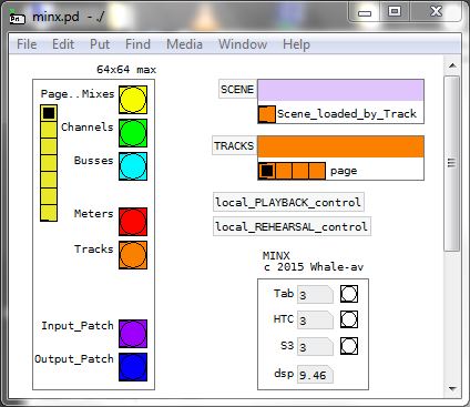
Minx
Xmas 2012 was pretty good.
I still had never heard of Pure Data or OSC.
I was still productive, just getting my computer booted for emails, sound and video editing etc.
And then it happened.
I was asked for a complete wireless stage monitoring system with control by the musicians, and the manufacturers for the professional market had nothing to offer at that time.
Data flow programming was made for me. I love it, and I cannot leave it alone.
I might not be very good at it, but I no longer do anything else.
Anyway, here is the current state of the project, for anyone who might find it useful.
It took longer to get around to writing the manual than it did to write the patches.
It is a fairly extreme example of the power of dynamic patching.
The patch is always dynamically built to the specification required.
There is some dynamic patching while it is running..... to change input and output routing.
The pronounced demise of extended forced an attempt at compliance with vanilla.
Every problem was resolved except the cookbook calcs for [biquad~] and I gave up and forgot about the conversion to Vanilla..
I had even built a dynamically created abstraction to replace [matrix~] from the cyclone library.
But now the ggee library is available through Deken for 64-bit Pd...
The Vanilla version has not been so extensively tested as the Extended version.
Minx could be used by a band for headphone monitoring in rehearsal too.
If you add a multitrack recorder/player it could be used for solo practice and a virtual soundcheck as well.
Anyway, here it is in its current state.
Extended...... Minx Extended.zip
Vanilla (requires ggee library)..... Minx Vanilla.zip
The Manual (written for the Extended version but valid for Vanilla)..... Minx Manual and Readme.zip
Batch files are a good way to start Pd as all the parameters can be set for the project.
They are not absolutely necessary, but your patch can be opened with different settings for different situations.
I have put a demo SCENE file (for 10 inputs / six outputs) and a demo TRACKS file so you can see it working straight away.
I have included only one short track so as to reduce download bloat...... the Manual is already more than twice as big as the patch....!
If you don't want to use TouchOSC then I am sure the remote controls can be built with Mobmuplat.
If you don't have a soundcard with 10 inputs and 6 outputs you will see some "connection failed" messages in the terminal...... but they are unimportant....... the patch will just be working for the inputs and outputs that you have.
David.
 posted in patch~
Best way to create random seed on [loadbang] with vanilla?
@Jona Yes, i believe at the core of each random algorithm is a cryptographic hash algorithm. A hash algorithm provides an output for each input in such a way that you cannot determine the input if you only know the output, even if you know the algorithm.
The only way to determine the input would be by brute force, that means calculating the outputs for all possible inputs within a given range and storing all input-output pairs in a huge so called rainbow table. With that you can look up the input for any output.
But other than that you cannot for example see any connection between hash(12) and hash(13). The inputs are close together, but the outputs are completely distinct.
With this you can generate a chain of numbers that seem completely random but are in fact mathematically determined. Only if you add outside unpredictable information, entropy, to the mix, the results can become truly random. Or at least have a random starting point if the entropy is added only in the beginning.
For actual cryptography it is crucial to get good entropy into the system, as the algorithms are usually known and well researched and every bit of information about the starting condition can help to decipher the encrypted code.
But for Pd purposes it doesn't have to be that complicated. The actual time would be enough, if only Pd had an object for that. ") In one of the examples above [time] from zexy was used. But again, there is the problem with raspberry pis that don't have internet access. They don't have a battery to keep a clock running when they are off, so they always start at the same date after booting. So of course you would have some different time after Pd has started, but it is not as reliable as it would seem at first glance.
In one of the examples above [time] from zexy was used. But again, there is the problem with raspberry pis that don't have internet access. They don't have a battery to keep a clock running when they are off, so they always start at the same date after booting. So of course you would have some different time after Pd has started, but it is not as reliable as it would seem at first glance.
 posted in technical issues
BELA & PD: Selecting between 2 routes for 1 analog input
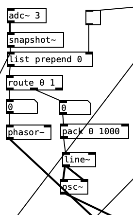
Hi! Relative beginner to PD here. I've been building a pretty basic synth which works fine in PD, but when loading it onto Bela I'm having issues with my analog inputs. With my current patch there is no sound and the connected potentiometers do nothing when turned.
The screenshot shows 2 oscillators which are controlled by one pot. (I am using sliders on the patch to simulate the analog inputs which worked fine for testing in the virtual environment) Essentially, I am using 7 analog inputs to control the frequencies of 14 oscillators. You can see in my screenshot how a toggle switches between two routes (all toggles are either on or off dependent on a master toggle which is my 8th analog input).
I think the reason this isn't working may be to do with using snapshot~ as a way to convert the signal to a control - I guess this isn't creating a continuous value which the patch can use for the frequencies of the oscillators? The list prepend object which defines the 2 routes obviously cannot take an input from the adc, so is there another way to convert this? Or is there some way I could have the input after the list? I've tried a few things out but can't get anything to work.
Thanks!
 posted in technical issues
Communicating from Arduino IDE to PD
Yep.. You can use comport. It be posible comunicate Pd and arduino.
Drymonitis have nice documentation to do that.
The tutorial "Arduino for PD'ers" is a good start: http://drymonitis.me/code/
He has a excelent book "Digital Electronics for Musicians" if you are interested you can try it to.
 posted in I/O hardware diy
[pix_share_read] and [pix_share_write] under windows
@whale-av, here is a log running pd with -lib Gem -verbose.
tried both 32bit and 64bit pd 0.48-1...
tried ./Gem.m_i386 and failed
tried ./Gem.dll and failed
tried ./Gem/Gem.m_i386 and failed
tried ./Gem/Gem.dll and failed
tried ./Gem.pd and failed
tried ./Gem.pat and failed
tried ./Gem/Gem.pd and failed
tried C:/Users/Raphael Isdant/Documents/Pd/externals/Gem.m_i386 and failed
tried C:/Users/Raphael Isdant/Documents/Pd/externals/Gem.dll and failed
tried C:/Users/Raphael Isdant/Documents/Pd/externals/Gem/Gem.m_i386 and failed
tried C:/Users/Raphael Isdant/Documents/Pd/externals/Gem/Gem.dll and failed
tried C:/Users/Raphael Isdant/Documents/Pd/externals/Gem.pd and failed
tried C:/Users/Raphael Isdant/Documents/Pd/externals/Gem.pat and failed
tried C:/Users/Raphael Isdant/Documents/Pd/externals/Gem/Gem.pd and failed
tried C:/Users/Raphael Isdant/AppData/Roaming/Pd/Gem.m_i386 and failed
tried C:/Users/Raphael Isdant/AppData/Roaming/Pd/Gem.dll and failed
tried C:/Users/Raphael Isdant/AppData/Roaming/Pd/Gem/Gem.m_i386 and failed
tried C:/Users/Raphael Isdant/AppData/Roaming/Pd/Gem/Gem.dll and failed
tried C:/Users/Raphael Isdant/AppData/Roaming/Pd/Gem.pd and failed
tried C:/Users/Raphael Isdant/AppData/Roaming/Pd/Gem.pat and failed
tried C:/Users/Raphael Isdant/AppData/Roaming/Pd/Gem/Gem.pd and failed
tried C:/Program Files/Common Files/Pd/Gem.m_i386 and failed
tried C:/Program Files/Common Files/Pd/Gem.dll and failed
tried C:/Program Files/Common Files/Pd/Gem/Gem.m_i386 and failed
tried C:/Program Files/Common Files/Pd/Gem/Gem.dll and failed
tried C:/Program Files/Common Files/Pd/Gem.pd and failed
tried C:/Program Files/Common Files/Pd/Gem.pat and failed
tried C:/Program Files/Common Files/Pd/Gem/Gem.pd and failed
tried D:/pd-0.48-1.windows.64bit/extra/Gem.m_i386 and failed
tried D:/pd-0.48-1.windows.64bit/extra/Gem.dll and failed
tried D:/pd-0.48-1.windows.64bit/extra/Gem/Gem.m_i386 and failed
tried D:/pd-0.48-1.windows.64bit/extra/Gem/Gem.dll and succeeded
D:\\pd-0.48-1.windows.64bit\\extra\\Gem\\Gem.dll: couldn't load
tried D:/pd-0.48-1.windows.64bit/extra/Gem.pd and failed
tried D:/pd-0.48-1.windows.64bit/extra/Gem.pat and failed
tried D:/pd-0.48-1.windows.64bit/extra/Gem/Gem.pd and failed
tried D:/pd-0.48-1.windows.64bit/doc/5.reference/Gem.m_i386 and failed
tried D:/pd-0.48-1.windows.64bit/doc/5.reference/Gem.dll and failed
tried D:/pd-0.48-1.windows.64bit/doc/5.reference/Gem/Gem.m_i386 and failed
tried D:/pd-0.48-1.windows.64bit/doc/5.reference/Gem/Gem.dll and failed
tried D:/pd-0.48-1.windows.64bit/doc/5.reference/Gem.pd and failed
tried D:/pd-0.48-1.windows.64bit/doc/5.reference/Gem.pat and failed
tried D:/pd-0.48-1.windows.64bit/doc/5.reference/Gem/Gem.pd and failed
Gem: can't load library```
posted in pixel#
EN-1 granular sampling synthesizer
@Joseph-Mikkelson in this case, you can connect switches and knobs directly to the Bela board, which has dedicated inputs for any type of digital or analog input. These can even run at signal rate for extremely accurate input, if you like!
Then when you install a PD patch on the Bela platform you can access the analog inputs (knobs) using the adc~ object - the 8 available analog inputs come up as adc~ numbers 3 to 10. Digital inputs (buttons) are accessed slightly differently, using a receive object (like "r Bela_digitalIn13).
There are other ways you can do this too, whether or not you use a Bela. For a Raspberry Pi, for example, I've found it easier to connect knobs/switches/sensors to something like a Teensy, which I code to turn into a USB MIDI controller, which is then connected to the Raspberry Pi which is running the PD patch (using ctlin and notein objects).
 posted in output~